Turntable for vacuum lens coating machine

A technology of vacuum coating machine and rotary table, applied in vacuum evaporation coating, sputtering coating, ion implantation coating and other directions, can solve the problem of low production efficiency, high average energy consumption per single piece, and it is difficult to meet modern scale production, etc. problems, to achieve the effect of reducing kinetic energy consumption and reducing wear and tear

Active Publication Date: 2015-05-27
DANYANG DINGXIN MASCH EQUIP CO LTD
View PDF5 Cites 4 Cited by
  • Summary
  • Abstract
  • Description
  • Claims
  • Application Information

AI Technical Summary

Problems solved by technology

[0002] The coating frame of the known lens vacuum coating machine is composed of a frame, a revolution mechanism and a number of rotation mechanisms. Due to each rotation mechanism, only one coating piece is placed Only one plated piece can be placed on the rod, and after the plated piece is finished, it is manually taken out from the stand, so its production efficiency is very low, and the average energy consumption of a single piece is high, which is difficult to meet the needs of modern scale production

Method used


Image

  • Turntable for vacuum lens coating machine

Examples


Embodiment Construction

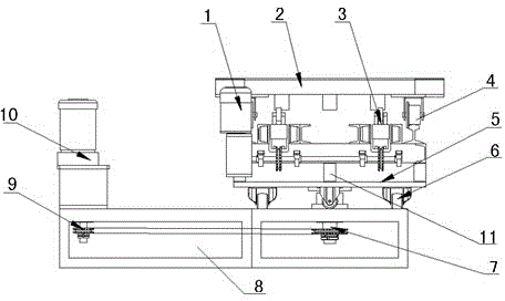
[0008] Depend on figure 1 Known, a lens vacuum coating machine Turntable , consisting of a pusher motor 1, a material trolley 2, a one-way pusher 3, an upper bracket 4, a rotating table 5, a load wheel 6, a rotation limit assembly 7, a base 8, a sprocket chain 9, a rotating motor 10, and a rotating shaft 11, the base 8 is fixed with a sprocket chain 9 transmission mechanism, the base 8 is provided with a rotating table 5 through two load wheels 6, the rotating table 5 can be rotated by the rotating shaft 11, and the rotating shaft 11 is located on the rotating shaft. The middle of the table 5 is connected with the chain, the rotary table 5 is provided with two upper brackets 4 and two one-way pushers 3, the material trolley 2 is fixed on the upper bracket 4, and the pushing motor 1 is placed on the ground. The rotary shaft 11 is provided with a rotation limit assembly 7, and the rotating motor 10 drives the rotary table 5 to rotate 180° through the transmission of the sprock...


PUM


Abstract

The invention relates to a turntable for a vacuum lens coating machine. The vacuum lens coating machine comprises a pushing motor (1), a material trolley (2), one-way pushers (3), an upper support (4), the turntable (5), bearing wheels (6), a rotation stop assembly (7), a base (8), a sprocket chain (9), a rotating motor (10) and a rotating shaft (11). The vacuum lens coating machine is characterized in that the rotation stop assembly (7) is arranged on the rotating shaft (11), the rotating motor (10) is used for driving the turntable (5) to rotate to the 180-degree position through the transmission of the sprocket chain (9), and the one-way pushers (3) on two sides are used for pushing the material trolley (2) to the next station by the simultaneous driving of the pushing motor (1) and the sprocket chain so as to transfer a lens on a coating rack of the vacuum lens coating machine. By adopting the turntable provided by the invention, the consumption of kinetic energy can be saved, the abrasion between related parts can be reduced, the coated lens can be rotated stably in the whole coating process, and the coating quality can be improved further.

Description

technical field [0001] The invention relates to a rotary table for a lens vacuum coating machine, which is suitable for use in the coating of the spectacle lens coating equipment. Background technique [0002] The coating frame of the known lens vacuum coating machine is composed of a frame, a revolution mechanism and several rotation mechanisms. Since each rotation mechanism has only one plated piece placement rod, only one plated piece can be placed. After the plated piece is finished, it is manually It is taken out from the stand, so its production efficiency is very low, and the average energy consumption of a single piece is high, which is difficult to meet the needs of modern scale production. Contents of the invention [0003] In view of the above deficiencies, the object of the present invention is to provide a rotary table for a lens vacuum coating machine. The rotary table is provided on the base through two bearing wheels, and the rotating motor drives the rota...

Claims


Application Information

Patent Timeline
Patent Type & Authority Applications(China)
IPC IPC(8): C23C14/50
CPCC23C14/505
Inventor 李时代包松养
Owner DANYANG DINGXIN MASCH EQUIP CO LTD
Why Eureka
Try Eureka