Underground continuous wall support replacement structure and construction method

A technology for underground diaphragm walls and construction methods, applied to underwater structures, infrastructure engineering, artificial islands, etc., can solve the problems of low reuse rate, consumption of consumables and labor, unfavorable demolition of underground diaphragm walls 11a, etc.

Active Publication Date: 2015-05-27
CHINA CONSTR EIGHT ENG DIV CORP LTD
View PDF4 Cites 4 Cited by
  • Summary
  • Abstract
  • Description
  • Claims
  • Application Information

AI Technical Summary

Problems solved by technology

Such a structure is not conducive to the demolition of the underground diaphragm wall 11a at first, and the basement floor 88 will be damaged during the demolition process; secondly, the construction needs repeated pouring and demolition,

Method used


Image

  • Underground continuous wall support replacement structure and construction method
  • Underground continuous wall support replacement structure and construction method
  • Underground continuous wall support replacement structure and construction method

Examples


Embodiment 1

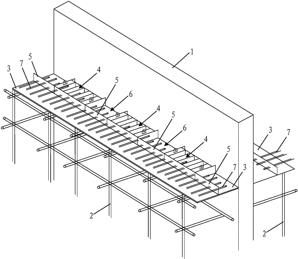
[0044] refer to figure 1 , is a schematic diagram of the three-dimensional structure of the first embodiment of the continuous wall support structure of the present invention. Such as figure 1 As shown, the present invention firstly provides a diaphragm wall replacement structure for pouring on both sides of the underground diaphragm wall 1 to form a basement floor, and facilitates butt jointing of the floor steel bars 7 extending out of the basement floor. The brace replacement structure includes a brace replacement unit erected between the underground diaphragm wall 1 and the pouring area of ​​the floor slab. The brace replacement unit includes: a vertical support 2 erected along the length direction of the underground diaphragm wall 1; a formwork 3 laid horizontally on On the bracket 2 and close to the wall surface of the underground diaphragm wall 1, the floor pouring area is formed on the formwork; a plurality of supporting bodies 4 are respectively arranged horizontal...

Embodiment 2

[0058] refer to Figure 9 , is a schematic diagram of the side structure of the second embodiment of the continuous wall brace structure of the present invention. refer to Figure 10 , for the corresponding Figure 9 Schematic diagram of the top view structure. combine Figure 9 and Figure 10 As shown, on the basis of Embodiment 1, a lying stiffening beam 46 is fixed between the first side plate 40 and the plurality of support beams 43, and between the second side plate 42 and the plurality of support beams 43. The stiffening beam 46 is an I-beam and is arranged along the length direction of the underground diaphragm wall 1. The upper and lower two stiffening beams 46 are stacked on top of each other. In this way, the structural strength of the supporting body 4 itself is increased.

[0059] The implementation process is also based on the first embodiment, after the floor steel bar 7 passes through the second side plate 42, it further passes through the stiffening beam ...

Embodiment 3

[0061] refer to Figure 11 , is a schematic diagram of the side structure of the third embodiment of the continuous wall brace structure of the present invention. refer to Figure 12 , for the corresponding Figure 11 Schematic diagram of the top view structure. combine Figure 11 and Figure 12 As shown, on the basis of Embodiment 2, a plurality of stiffening plates 47 are fixed and tightened between the flanges of the stiffening beams 46, and the stiffening plates 47 are perpendicular to the wall surface of the underground diaphragm wall 1 to further strengthen the supporting body. 4 Its own structural strength can withstand greater pouring extrusion force.

[0062] The implementation process is basically the same as the implementation process of the second embodiment, so it will not be repeated here.


PUM


Abstract

The invention provides an underground continuous wall support replacement structure and a construction method, wherein the underground continuous wall support replacement structure comprises an underground continuous wall, floor slab casting areas and support replacement units; the floor slab casting areas are located at the sides of the underground continuous wall, and each floor slab casting area comprises a formwork and floor slab rebars arranged on the formwork; the support replacement units are arranged on the formworks and located between the floor slab casting areas and the underground continuous wall, each support replacement unit comprises a plurality of support replacement bodies, and the support replacement bodies are arranged at intervals along the length direction of the underground continuous wall; each support replacement body comprises a first support end and a second support end, the first support end abuts against the underground continuous wall, an isolating strip is arranged between the second support ends of each two neighboring support replacement bodies, so that a side formwork of the floor slab casting area is formed, and at least part of the floor slab rebars run through the second support ends to form connecting sections. The invention utilizes the underground continuous wall to build supports and arranges the underground continuous wall support replacement structure, a basement floor slab is then formed by casting and the floor slab rebars are connected, consequently, the difficulty of support replacement construction is decreased, and the efficiency and quality of construction are further increased.

Description

technical field [0001] The invention specifically relates to an underground continuous wall supporting structure and a construction method thereof. Background technique [0002] In the basement construction of a building construction project, due to reasons such as site, safety or funds, it is often necessary to carry out staged construction. The underground diaphragm wall is often used as a separate enclosure structure for staged construction. into one. In order to ensure that the basement can be connected to each other as a whole, it is necessary to deal with the problem of changing the support in the early and late construction parts. [0003] At present, the existing construction method of brace replacement is relatively rough and simple, without more detailed nodes, and the ends of steel bars cannot be overlapped or staggered by a certain length. Such as Figure 13 , in the existing common actual construction, the basement floor slab 88 is directly connected to the un...

Claims


Application Information

Patent Timeline
IPC IPC(8): E02D29/02
Inventor 张忠良莫兴虎俞宏伟
Owner CHINA CONSTR EIGHT ENG DIV CORP LTD
Why Eureka
Try Eureka