Spring buffer type pneumatic executing mechanism

A pneumatic actuator and spring cushioning technology, which is applied in the direction of engine components, mechanical equipment, fluid pressure actuators, etc., can solve the position where the pneumatic control valve cannot meet the use requirements and does not allow the pneumatic control valve to violently hit, open and close Hysteresis and other problems, to achieve the effect of ingenious structure, small buffer stroke, and small installation space

Active Publication Date: 2015-05-27
WUXI SMART AUTO CONTROL ENG CO LTD
View PDF4 Cites 3 Cited by
  • Summary
  • Abstract
  • Description
  • Claims
  • Application Information

AI Technical Summary

Problems solved by technology

[0002] At present, there are more and more occasions where pneumatic control valves are used for frequent switching and fast cut-off control. However, in actual use, some pneumatic control valves have special structures such as soft valve seats or sharp-angle sealing valve seats, which do not allow pneumatic control valves to be violent. strike
In addition, when the circulating medium is a flammable and explosive special medium, it is easy to generate sparks due to collision and cause accidents, and violent impact of the pneumatic control valve is not allowed.
In this way, in the occasions that require frequent switching and quick cut-off control, the pneumatic control valve using the existing conventional pneumatic actuator can no longer

Method used


Image

  • Spring buffer type pneumatic executing mechanism
  • Spring buffer type pneumatic executing mechanism

Examples


Embodiment Construction

[0018] The present invention will be further described below in conjunction with specific drawings and embodiments.

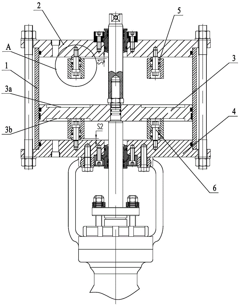
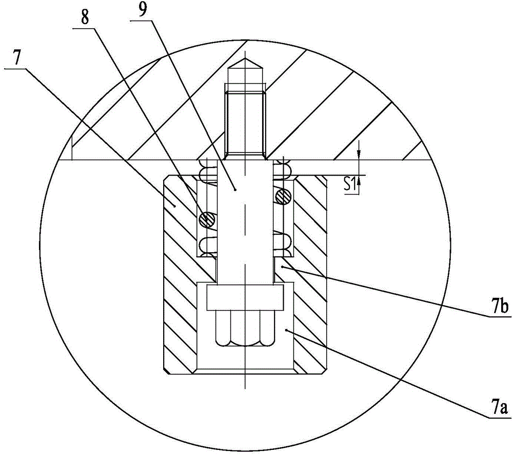
[0019] As shown in the figure: the spring-buffered pneumatic actuator in the embodiment is improved from the existing conventional piston-type pneumatic actuator. The piston-type pneumatic actuator mainly includes a cylinder body 1, an upper cylinder head 2, a lower cylinder Cover 3 and piston 4, the inner plane of the upper cylinder head 2 is provided with several upper spring buffer units 5 evenly distributed in the circumferential direction, and the upper spring buffer unit 5 cooperates with the upper surface of the piston 4 to provide the upward movement of the pneumatic actuator. Provide a buffering effect; the inner plane of the lower cylinder head 3 is provided with several lower spring buffer units 6 evenly distributed in the circumferential direction, and the lower spring buffer units 6 cooperate with the lower surface of the piston 4 to provide the dow...


PUM


Abstract

The invention relates to a spring buffer type pneumatic executing mechanism. The spring buffer type pneumatic executing mechanism comprises an existing conventional piston type pneumatic executing mechanism, wherein the piston type pneumatic executing mechanism comprises a cylinder block, an upper cylinder cover, a lower cylinder cover and a piston. The spring buffer type pneumatic executing mechanism is characterized in that a plurality of upper spring buffer units which are uniformly distributed along the circumferential direction are arranged on the inner plane of the upper cylinder cover; the upper spring buffer units are matched with the upper surface of the piston, and are used for buffering the upward action of the pneumatic executing mechanism; a plurality of lower spring buffer units which are uniformly distributed along the circumferential direction are arranged on the inner plane of the lower cylinder cover; the lower spring buffer units are matched with the lower surface of the piston, and are used for buffering the downward action of the pneumatic executing mechanism. The spring buffer type pneumatic executing mechanism is skillful in structure, is reasonable in design, can be applied to the occasion of rapid and frequent actions, is accurately controllable in buffer stroke, has a small buffer stroke, and does not influence the response speed of the pneumatic executing mechanism; the pneumatic executing mechanism has a spring buffer function at the starting point and end point of the stroke.

Description

technical field [0001] The invention relates to a pneumatic actuator, in particular to a spring buffer type pneumatic actuator. Background technique [0002] At present, there are more and more occasions where pneumatic control valves are used for frequent switching and fast cut-off control. However, in actual use, some pneumatic control valves have special structures such as soft valve seats or sharp-angle sealing valve seats, which do not allow pneumatic control valves to be violent. hit. In addition, when the circulating medium is a flammable and explosive special medium, it is easy to generate sparks due to collision and cause accidents, and violent impact of the pneumatic control valve is not allowed. In this way, in the occasions that require frequent switching and quick cut-off control, the pneumatic control valve using the existing conventional pneumatic actuator can no longer meet the requirements of use, which requires the design of a pneumatic actuator with a buf...

Claims


Application Information

Patent Timeline
IPC IPC(8): F16K31/122F15B15/22
CPCF15B15/22F16K31/122
Inventor 陈彦邓传湖陆坤铭
Owner WUXI SMART AUTO CONTROL ENG CO LTD
Why Eureka
Try Eureka