
Quick coordinate positioning method for three-dimensional laser detection system of underground vacant area

A three-dimensional laser and detection system technology, applied in the direction of measuring devices, optical devices, instruments, etc., can solve problems such as difficulty in moving equipment, reducing scanning efficiency in empty areas, difficulties, etc., to save labor costs and material costs, and improve scanning efficiency , the result is accurate

Inactive Publication Date: 2015-05-27
NORTHEASTERN UNIV
View PDF5 Cites 10 Cited by
  • Summary
  • Abstract
  • Description
  • Claims
  • Application Information

AI Technical Summary

Problems solved by technology

[0004] (1) It is difficult to move the equipment
Existing positioning methods require a variety of supporting devices, and the device components are many, and most of them are slender rods. Due to the narrow underground working space of mines, it takes time and effort to carry and transfer
[0005] (2) High measurement environment requirements
In the existing method, before setting up the equipment, it is necessary to find a relatively spacious, safe, and wide-viewing place at the entrance of the empty space in advance. In the narrow underground space, it is often difficult to achieve this requirement, and the operation is very inconvenient.
[0006] (3) The installation and disassembly process is cumbersome
The underground gobs of mines are widely distributed and the number is large. After measuring a goaf, it is necessary to transfer the equipment to the next measurement point for new measurement. During this process, these components need to be disassembled and assembled continuously. This process is relatively It is cumbersome, so it consumes a lot of working time and seriously reduces the efficiency of empty area scanning

Method used


Image

  • Quick coordinate positioning method for three-dimensional laser detection system of underground vacant area
  • Quick coordinate positioning method for three-dimensional laser detection system of underground vacant area
  • Quick coordinate positioning method for three-dimensional laser detection system of underground vacant area

Examples


Embodiment Construction

[0019] Below in conjunction with embodiment and accompanying drawing, the present invention is described in further detail:

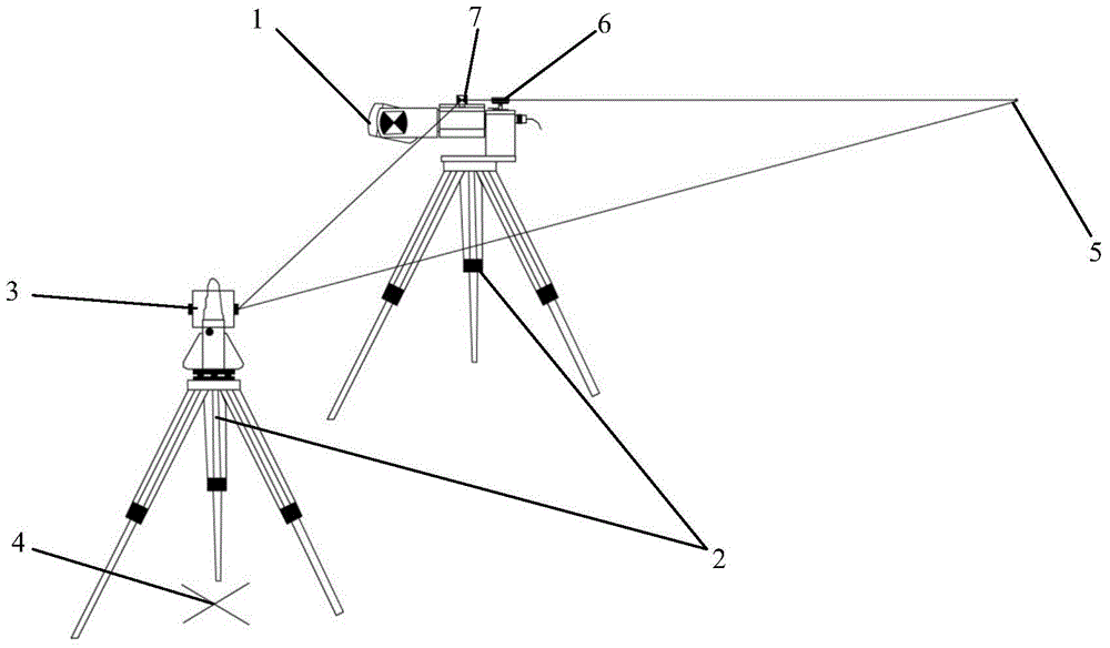
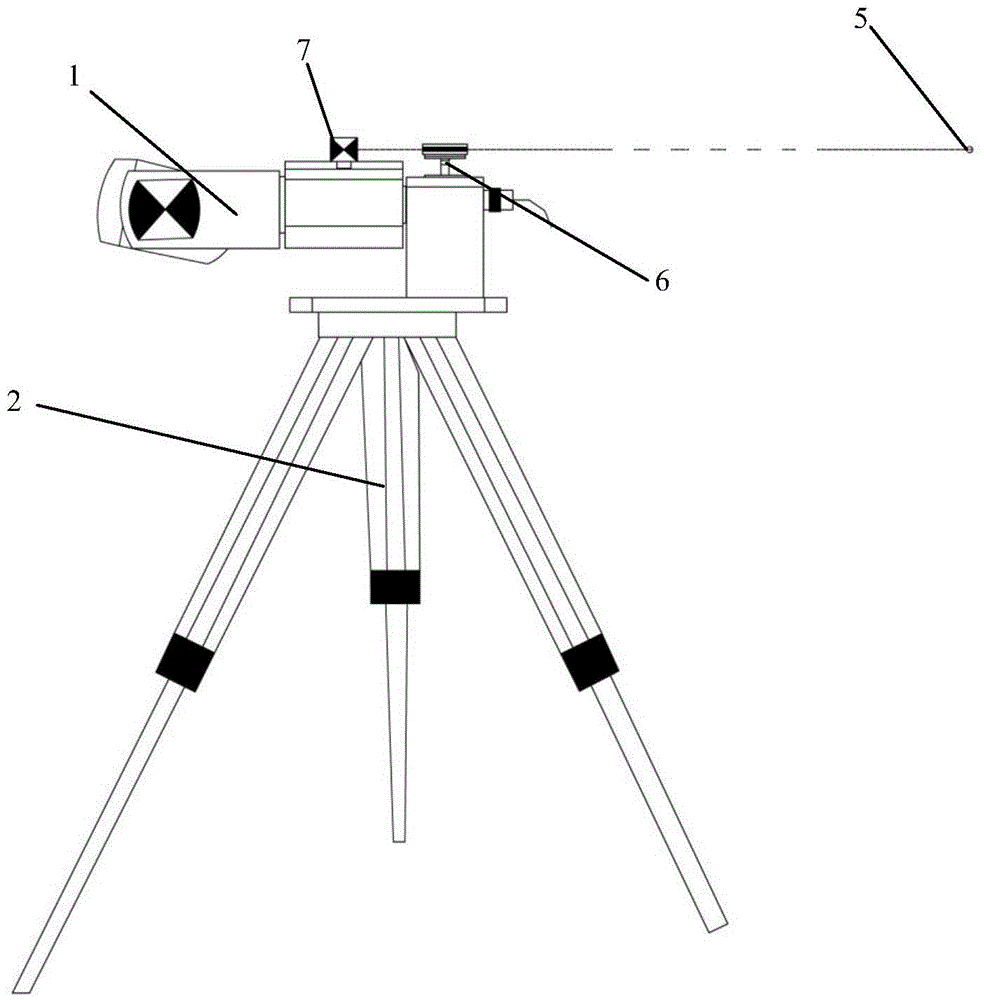
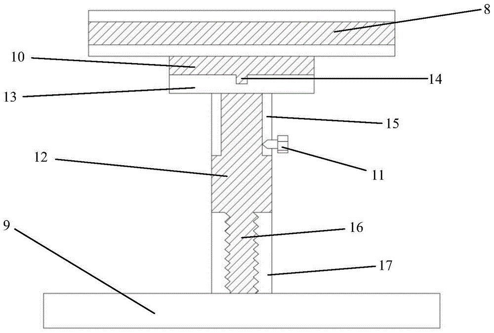
[0020] Such as Figure 1 ~ Figure 3 As shown, a coordinate fast positioning method for a three-dimensional laser detection system in an underground empty area includes the following steps:

[0021] Preliminary preparations: First, set up the 3D laser scanning equipment head 1 and the total station 3. The selection of the erection point should refer to the actual situation of the mine empty area, and comprehensively consider factors such as safety, ease of equipment erection, and ease of measuring the coordinates of the front and rear target points. Select one or more erection sites in the area.

[0022] Erection of the 3D laser scanning equipment head 1: choose a dry and flat ground to set up the tripod 2, use the leveling device on the tripod 2 to level the tripod 2; install the 3D laser scanning equipment head 1 on the tripod 2, The front target 7 i...


PUM


Abstract

The invention discloses a quick coordinate positioning method for a three-dimensional laser detection system of an underground vacant area, and belongs to the technical field of underground mine surveying and mapping. The method comprises the following steps: 1, setting a front target at a target position on a three-dimensional laser scanning equipment head; 2, generating a laser reference point on the rock wall right behind the three-dimensional laser scanning equipment head by a laser ranging and positioning device mounted on the three-dimensional laser scanning equipment head; 3, positioning the absolute coordinates of the three-dimensional laser scanning equipment head by measuring the absolute coordinates of the front target and the laser reference point by a non-prism mode of a total-station instrument so as to transform a point cloud under a local coordinate system scanned by the three-dimensional laser scanning equipment head into a point cloud under a world coordinate system. The method is easy, convenient and quick for positioning, and the result is accurate; the labor cost and the material cost are reduced, and the scanning efficiency is improved.

Description

Technical field: [0001] The invention belongs to the technical field of underground mine surveying and mapping, and in particular relates to a quick coordinate positioning method for a three-dimensional laser detection system in an underground empty area. Background technique: [0002] The existence of a large number of goafs deteriorates the mining conditions of mines, causing deformation and damage of ore pillars. What is more serious is that disasters such as large-scale underground caving, rock movement, surface subsidence, and water inrush caused by goafs may cause serious casualties. and equipment damage, posing a serious threat to mine safety production. The empty area 3D laser detection system (CMS) is a non-contact active measurement system that uses laser as the measurement medium to collect large-area, high-density, and large-space 3D data, thereby truly describing the overall structure and location of the target. Morphological properties. Compared with traditio...

Claims


Application Information

Patent Timeline
Patent Type & Authority Applications(China)
IPC IPC(8): G01B11/00
Inventor 徐帅王运森闫腾飞李元辉安龙张驰唐忠伟
Owner NORTHEASTERN UNIV
Learn More