
A phase-enhanced thin film thickness measurement method and system

A film thickness enhancement technology, applied in the field of phase enhancement film thickness measurement, can solve the problems of limited precision, high frequency film roughness, unsatisfactory film step preparation, large error rate, etc., and achieve the effect of reducing the impact

Active Publication Date: 2017-07-25
ZHEJIANG UNIV
View PDF7 Cites 0 Cited by
  • Summary
  • Abstract
  • Description
  • Claims
  • Application Information

AI Technical Summary

Problems solved by technology

This method has the following disadvantages: it is necessary to prepare a film thickness step used for testing, and the accuracy of this method is limited by the size of the probe used, and there will be an integral smoothing effect when testing the surface profile of the film, similar to Because of mathematical low-pass filtering, it is impossible to obtain good test results for samples with unsatisfactory preparation of high-frequency film roughness and film steps.
4. The detection spectrum is wide
However, the optical thin film phase method is limited by the sensitivity of the nonlinear phase of the thin film (that is, the difference between the maximum value and the minimum value of the nonlinear phase of the thin film), and the minimum thin film thickness measurement that can be accurately and repeatedly realized theoretically is only 0.18 μm
When the thickness of the film is less than 0.18μm, using this method to measure the film thickness may bring a large error, and the error rate is greater than 1%.

Method used


Image

  • A phase-enhanced thin film thickness measurement method and system
  • A phase-enhanced thin film thickness measurement method and system
  • A phase-enhanced thin film thickness measurement method and system

Examples


Embodiment Construction

[0040] The present invention will be further described below in conjunction with the accompanying drawings and embodiments.

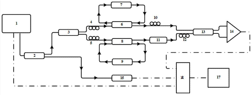
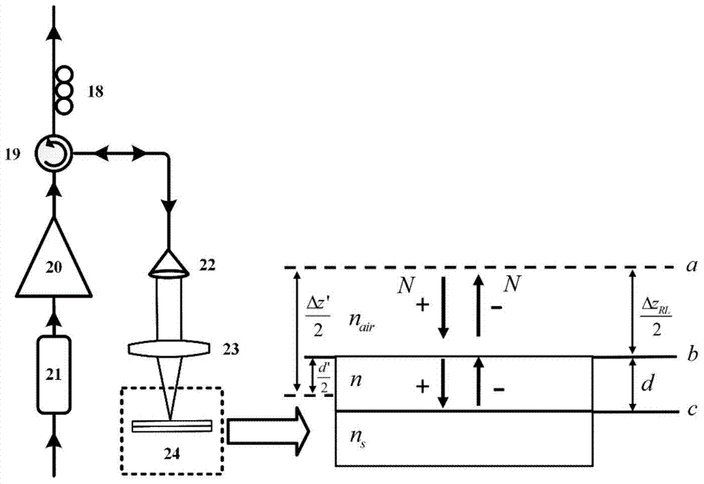
[0041] Such as figure 1 As shown, the present invention includes a broadband sweeping light source 1, a first broadband fiber coupler 2, a second broadband fiber coupler 3, a first polarization controller 4, a second polarization controller 5, a third broadband fiber coupler 6, Measurement sub-cycle cavity 7, fourth broadband fiber coupler 8, reference sub-cycle cavity 9, third polarization controller 10, fiber delay line 11, fourth polarization controller 12, fifth broadband fiber coupler 13, first high A bandwidth-balanced photodetector 14 , a sampling wavenumber drift correction unit 15 , a high-speed data acquisition card 16 , and a computer 17 .

[0042] The broadband sweeping light source 1 is connected to the input end of the second broadband fiber coupler 3 and the input end of the sampling wave number drift correction unit 15 respectively throug...


PUM


Abstract

The invention discloses a method and a system for measuring the thickness of a phase-enhanced film. The system adopts a broadband frequency sweep light source; a measuring sub-cycling cavity and a reference sub-cycling cavity are respectively formed in a measuring light path and a reference light path; when measuring light and reference light are utilized for high-speed (optical-speed) light cycling in the measuring and reference sub-cycling cavities, the film phases at same transverse positions of film samples to be measured can be accumulated, amplified and measured (the amplification factor equals to the light cycling grade of the measuring light and that of the reference light), so that the sensitivity of film phase detecting can be improved; moreover, during accumulation, amplification and measuring of the film phases, a measuring light beam always illuminates the same transverse positions of the film samples to be measured, so that the film phase enhancement method can be different from the spectroscopic method that the measuring light beam is utilized for multiple reflection to obtain the film reflectivity, and the capability, to perform lateral resolution on the film samples to be measured, of the system cannot be reduced.

Description

technical field [0001] The invention relates to the field of optical coherence measurement, in particular to a phase-enhanced film thickness measurement method and system. Background technique [0002] The importance of thin film technology in modern science and technology is increasing day by day. In recent decades, various optoelectronic devices, bio-sensing technologies, laser devices, microelectronic devices, liquid crystal displays, and integrated optics have largely relied on the development of thin-film technology. With the continuous development of optical thin film design and thin film technology, it is necessary to accurately measure several main optical parameters of optical thin films when preparing high-performance optical thin film components, including: refractive index, film thickness, transmittance, reflectance and absorption. than wait. Among them, the physical thickness of the film is one of the most basic parameters of the film, which will affect the fi...

Claims


Application Information

Patent Timeline
Patent Type & Authority Patents(China)
IPC IPC(8): G01B11/06G02B27/28
Inventor 丁志华沈毅陈志彦赵晨鲍文李鹏
Owner ZHEJIANG UNIV
Learn More