Electromagnetic inspection method based on hall sensor array and electromagnetic inspection system based on hall sensor array

A Hall sensor and array technology, applied in the direction of material magnetic variables, etc., can solve the problems of high surface smoothness requirements, small detection range, and influence on magnetic particles, etc., to increase the application range and detection speed, and improve detection efficiency , to avoid the effect of waste and pollution

Inactive Publication Date: 2015-05-27
河南省锅炉压力容器安全检测研究院
View PDF3 Cites 24 Cited by
  • Summary
  • Abstract
  • Description
  • Claims
  • Application Information

AI Technical Summary

Problems solved by technology

These two methods have high requirements on the surface smoothness of the test piece, high requirements on the technology and experience of the test personnel, and the detection range is small and the speed is slow.
Regardless of whether it is a dry method or a wet method, the magnetic powder used for detection will be adsorbed on the surface of the detected workpiece due to its own remanence, which

Method used


Image

  • Electromagnetic inspection method based on hall sensor array and electromagnetic inspection system based on hall sensor array
  • Electromagnetic inspection method based on hall sensor array and electromagnetic inspection system based on hall sensor array
  • Electromagnetic inspection method based on hall sensor array and electromagnetic inspection system based on hall sensor array

Examples


Embodiment Construction

[0048] The present invention will be further described below with reference to the accompanying drawings and specific embodiments.

[0049] In order to make the objectives, technical solutions and advantages of the present invention clearer, the present invention will be further described in detail with reference to the accompanying drawings and embodiments. It should be understood that the specific embodiment described in the present invention is only a preferred manner, and is only used to explain the present invention, but not to limit the present invention in any way.

[0050] The invention provides a method and system for electromagnetic flaw detection, and the following steps are involved in using this flaw detection method:

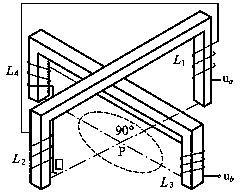
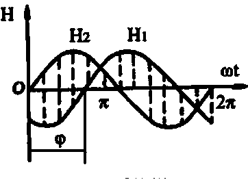
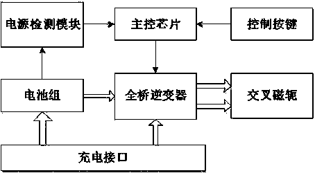
[0051] S01: The full-bridge inverter inverts the input DC power into AC power with controllable frequency, and provides AC currents with no less than two different frequencies to the cross yoke in each unit magnetization cycle;

[...


PUM


Abstract

The invention relates to an electromagnetic inspection system which comprises a magnetic field generation device and a magnetic field detection device, wherein the magnetic field detection device inspects a magnetic induction component through detecting a magnetic field generated by the magnetic field generation device; the magnetic field generation device mainly comprises a full-bridge inverter, a main control chip, a cross magnet yoke and a power supply detection module, and is mainly used for generating an electromagnetic field for magnetizing a workpiece; and the magnetic field detection device comprises a hall sensor array, a data acquisition module, a data processing module and a data display module, and is used for detecting and displaying magnetic lines generated around the workpiece by the magnetic field generation device. By virtue of the electromagnetic inspection system, the defects of a magnetic powder inspection mode in a nondestructive detection process are overcome; the detection time and detection range of single charging are prolonged and improved; and the detection rate and detection speed of the single charging are increased.

Description

technical field [0001] The invention relates to a non-destructive testing system, in particular to an electromagnetic flaw detection method and system based on a Hall sensor array. Background technique [0002] As a mature non-destructive testing method, magnetic particle inspection has been widely used in various fields at home and abroad. The basic principle of magnetic particle inspection is: the magnetic permeability of ferromagnetic materials is much greater than that of non-ferromagnetic materials. To analyze the magnetic flux density β=μH, B magnetic force lines pass through the unit area of ​​the workpiece, but B magnetic force lines cannot be allowed to pass through the unit area of ​​the defect area, forcing a part of the magnetic force lines to squeeze into the material below the defect, and others The magnetic field lines have to be forced to escape from the surface of the workpiece to form magnetic flux leakage, and the magnetic powder will be attracted by the ...

Claims


Application Information

Patent Timeline
IPC IPC(8): G01N27/84
Inventor 黄新超李文广禹红丽吴红英
Owner 河南省锅炉压力容器安全检测研究院
Why Eureka
Try Eureka