
Transparent conductive structure with metal grid

A metal grid, transparent and conductive technology, applied in the direction of transparent dielectric, conductive pattern layout details, dielectric properties, etc., can solve problems such as silver ion migration

Inactive Publication Date: 2015-05-27
INTERFACE OPTOELECTRONICS SHENZHEN +1
View PDF7 Cites 2 Cited by
  • Summary
  • Abstract
  • Description
  • Claims
  • Application Information

AI Technical Summary

Problems solved by technology

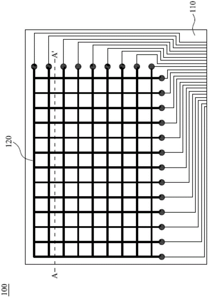
[0005] Based on this, in order to solve the migration phenomenon of silver ions produced by traditional transparent conductive structures, it is necessary to provide a transparent conductive structure to solve the problems encountered by transparent conductive structures with metal grids for a long time

Method used


Image

  • Transparent conductive structure with metal grid
  • Transparent conductive structure with metal grid
  • Transparent conductive structure with metal grid

Examples


Embodiment Construction

[0031] Next, the present invention will be described in detail with embodiments and accompanying drawings. In the drawings or descriptions, the same symbols or numbers are used for similar or identical parts. In the drawings, the shapes or thicknesses of the embodiments may be exaggerated for simplification or convenient labeling, and parts of components in the drawings will be described in words. It is understood that components not shown or described are of various styles known to those of ordinary skill in the art.

[0032] The terminology used herein is for the purpose of describing particular embodiments only and is not intended to be limiting of the invention. As used herein, the singular forms "a", "an" and "the" also include plural forms unless the context clearly dictates otherwise. It should be further understood that when used in this specification, the term "comprising" (comprises and / or comprising) specifies the presence of the described features, integers, steps...


PUM

PropertyMeasurementUnit
thicknessaaaaaaaaaa
thicknessaaaaaaaaaa

Abstract

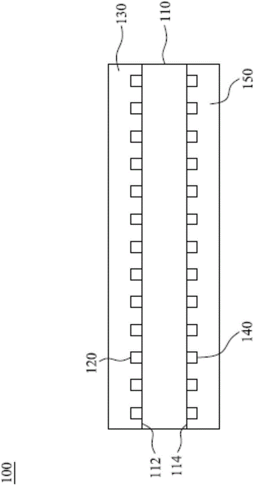
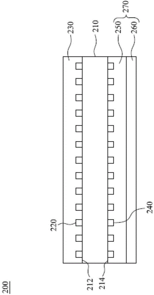
The invention provides a transparent conductive structure with a metal grid. The transparent conductive structure comprises a transparent substrate, a first metal grid structure, a first transparent insulating layer, a second metal grid structure and a second transparent insulating layer, wherein the transparent substrate is provided with an upper surface and a lower surface opposite to the upper surface; the first metal grid structure is arranged on the upper surface of the transparent substrate; the first transparent insulating layer encircles the first metal grid structure and covers the upper surface of the transparent substrate; the second metal grid structure is arranged on the lower surface of the transparent substrate; the second transparent insulating layer encircles the second metal grid structure and covers the lower surface of the transparent substrate. The transparent conductive structure is provided with the first and second transparent insulating layers, and moisture in an environment can be isolated so as to be prevented from reacting with the first and second metal grid structures to cause metal ion migration.

Description

technical field [0001] The invention relates to a transparent conductive structure with a metal grid, in particular to a transparent conductive structure with a transparent insulating film. Background technique [0002] In the past, most common touch panels used indium tin oxide (ITO) as the transparent conductive material. However, compared with the resistance value of metal, the surface resistance value (150-400Ω / □) and line resistance value (10,000-50,000Ω / □) of ITO are both higher. When the area of ​​the touch panel is larger, the total surface resistance of the touch panel also increases. In this way, the response speed of the touch panel is reduced, or the sensitivity is not good. Therefore, touch panels with metal grids made of silver as a conductive material have gradually replaced traditional ITO touch panels. [0003] Although silver has a very small resistance value, silver itself has relatively large chemical activity, so it is easy to dissociate silver ions f...

Claims


Application Information

Patent Timeline
Patent Type & Authority Applications(China)
IPC IPC(8): G06F3/041
CPCG06F3/0416G06F2203/04103H05K1/0289H05K1/0298H05K2201/0108H05K1/0274G06F2203/04112G06F3/0446G06F3/0445G06F3/041G06F2203/04107
Inventor 虞精兵林泰吾
Owner INTERFACE OPTOELECTRONICS SHENZHEN
Learn More