Motion capture method based on inertia and optical measurement fusion

An optical measurement and motion capture technology, applied in image data processing, instruments, 3D modeling, etc., can solve problems such as error accumulation, occlusion interference, data drift, etc., to solve occlusion and use environment restrictions, and increase effective data information The effect of volume and fusion efficiency

Inactive Publication Date: 2015-05-27
ENG DESIGN RES INST OF SECOND ARTILLERY PLA +1
View PDF3 Cites 37 Cited by
  • Summary
  • Abstract
  • Description
  • Claims
  • Application Information

AI Technical Summary

Problems solved by technology

Specifically, the present invention effectively solves the inherent error accumulation, data drift, and poor dynamic tracking performance of inertial measurement units (IMUs) by fusing optical measurements; etc.) and occlusion interference; the number and type of sensing units can be expanded; one or more objects can be captured at the same time; real-time data acquisition, transmission, processing, and error correction can be realized

Method used


Image

  • Motion capture method based on inertia and optical measurement fusion
  • Motion capture method based on inertia and optical measurement fusion
  • Motion capture method based on inertia and optical measurement fusion

Examples


Embodiment Construction

[0054] In order to make the purpose, technical solutions and advantages of the present invention more clear, the specific embodiments provided below in conjunction with the accompanying drawings are intended as descriptions of examples of the present invention. It should be understood that the specific embodiments described here are only used to explain the present invention, not to limit the present invention.

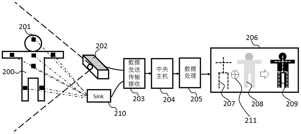
[0055] The motion capture method based on the fusion of inertial and optical measurements proposed by the present invention is characterized in that the method fuses data obtained by inertial measurement motion capture and optical measurement motion capture. attached figure 1 It shows a schematic diagram of the inertial measurement and optical measurement fusion method provided by the embodiment of the present invention, specifically including:

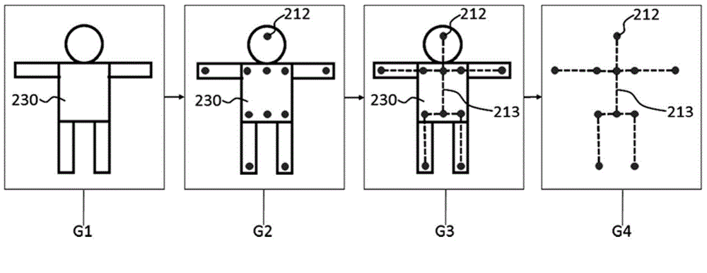
[0056] Inertial measurement unit 201: used to estimate the spatial attitude information of the captured object, including ...


PUM


Abstract

The invention discloses a motion capture method based on inertia and optical measurement fusion, and relates to the field of a sensing technology and computer vision, in particular to capture and analysis of motion processes of one or more objects. An inertia measurement technology and an optical capture technology are combined. The inertia measurement technology has the characteristics that the inertia measurement technology is insusceptible to the external environment, but problems of error accumulation, data drifting, poorer dynamic tracking performance and the like exist during measurement; the optical motion capture technology is high in accuracy but is limited by the environment such as illumination, colors and the like easily and interfered by shielding. The motion capture system and method integrate advantages of the inertia measurement technology and the optical capture technology, are low in cost, high in accuracy, small in error and insusceptible to the environment and are not interfered by shielding.

Description

technical field [0001] The invention belongs to the field of sensor technology and computer vision, in particular to a high-precision motion capture method based on multi-sensor fusion. Background technique [0002] Motion capture technology refers to the use of specific technical means to truly restore the posture, position and trajectory of moving objects. This technology is widely used in military simulation, medical rehabilitation, virtual reality, ergonomics, film and television animation, games and other fields, such as: [0003] [1] Bruderlin et al., Motion signal processing, Proceedings of SIGGRAPH 95, pp.105-108, 1995; [0004] [2] Gleicher, Retargeting motion to new characters, Proceedings of SIGGRAPH 98, PP.33-42, 1998; [0005] [3]Kovar et al.,Motion graphs,ACM Transactions on Graphics 21,3,pp.4763-482,2002,Arkan et al.,Motion synthesis from annotations,pp.402-408,2003. [0006] After decades of development, motion capture technology has become more and more m...

Claims


Application Information

Patent Timeline
Patent Type & Authority Applications(China)
IPC IPC(8): G06T7/20G06T17/00
CPCG06T7/207G06T17/00
Inventor 费允锋田庆龙宋银灏孙广毅李吉许林张瑒
Owner ENG DESIGN RES INST OF SECOND ARTILLERY PLA
Why Eureka
Try Eureka