

Ejector pin mechanism and plasma processing equipment
A thimble and workpiece technology, which is applied in the manufacture of semiconductor/solid-state devices, discharge tubes, electrical components, etc., can solve the problems of the complex structure of the thimble mechanism 16, the low adjustment precision, and the complex adjustment process, so as to shorten the level adjustment time and improve the Levelness, the effect of improving process quality
- Summary
- Abstract
- Description
- Claims
- Application Information
AI Technical Summary
Problems solved by technology
Method used
Image

Examples
Embodiment Construction
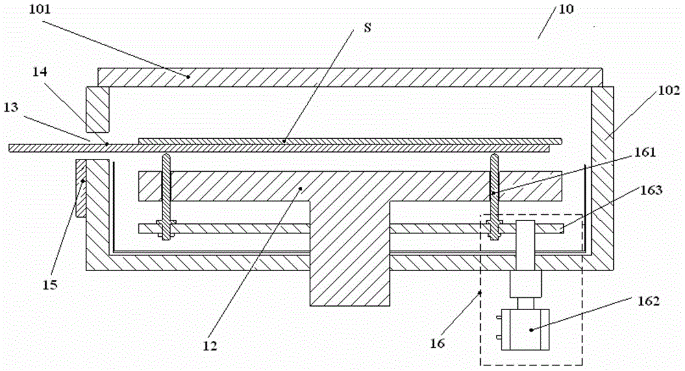
[0028] In order for those skilled in the art to better understand the technical solutions of the present invention, the thimble mechanism and plasma processing equipment provided by the present invention will be described in detail below with reference to the accompanying drawings.
[0029] Figure 4 The perspective view of the thimble in the thimble mechanism provided by the first embodiment of the present invention. Figure 5 for along Figure 4 The cross-sectional view of line A-A' in the middle. Please also refer to Figure 4 and Figure 5 , the thimble mechanism includes at least three thimbles 20 and a bracket for supporting the thimble 20, an elastic member 21 is arranged between each thimble 20 and the bracket, and the height of the elastic member 21 can be within the elastic range under pressure changes, and the height of the thimble 20 relative to the bracket changes.
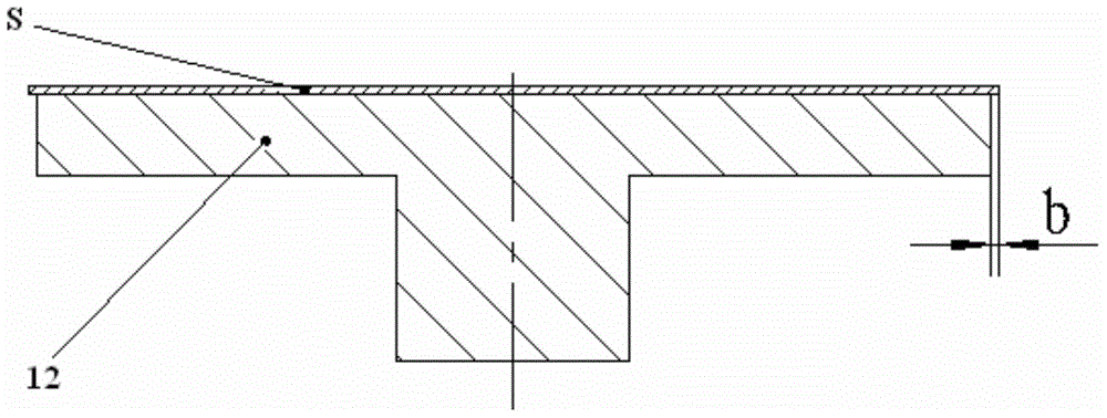
[0030] Combine below Figure 5Describe in detail the specific structure among the thimble 20...
PUM
 Abstract
Description
Claims
Application Information