Large-scale photovoltaic power station reactive voltage control method

A voltage control method and photovoltaic power station technology, applied in photovoltaic power generation, reactive power compensation, AC network voltage adjustment, etc., can solve problems such as unfavorable photovoltaic power station stable operation, high PVGU voltage, inverter off-grid, etc.

Active Publication Date: 2015-05-27
CHONGQING UNIV
View PDF3 Cites 9 Cited by
  • Summary
  • Abstract
  • Description
  • Claims
  • Application Information

AI Technical Summary

Problems solved by technology

[0005] Although there is no specific regulation on the PVGU grid-connected voltage in the station, due to the existence of the collector line in the station, with the increase of active power output, the voltage of the PVGU at the end of the line may be too high, resulting in the action of the protection device and making the inverter If the device is off-grid, it is not conducive to the stable operation of the photovoltaic power station

Method used


Image

  • Large-scale photovoltaic power station reactive voltage control method
  • Large-scale photovoltaic power station reactive voltage control method
  • Large-scale photovoltaic power station reactive voltage control method

Examples


Embodiment 1

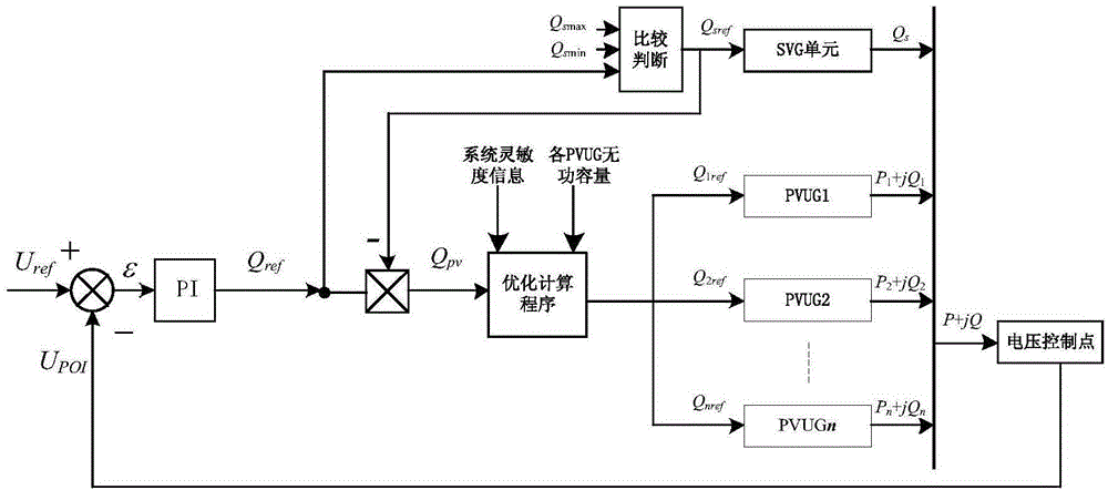
[0048]In order to facilitate centralized compensation, photovoltaic power plants usually set reactive power compensation devices on the low-voltage side of the main transformer. The "Technical Specifications for Reactive Power Compensation of Photovoltaic Power Stations (Draft for Comment)" stipulates that the reactive power output capacity of the inverter should be fully utilized, so large-scale The reactive power control of photovoltaic power plants must involve the coordinated control between reactive power compensation devices and photovoltaic inverters and between different inverters. In view of the dynamic reactive power adjustment capability of the static var generator SVG in reactive power compensation, this embodiment only uses the SVG instead of the reactive power compensation device for analysis and design. Since both the SVG and the inverter can realize reactive power output by adjusting the reactive power reference, based on this, the following control methods are ...

Embodiment 2

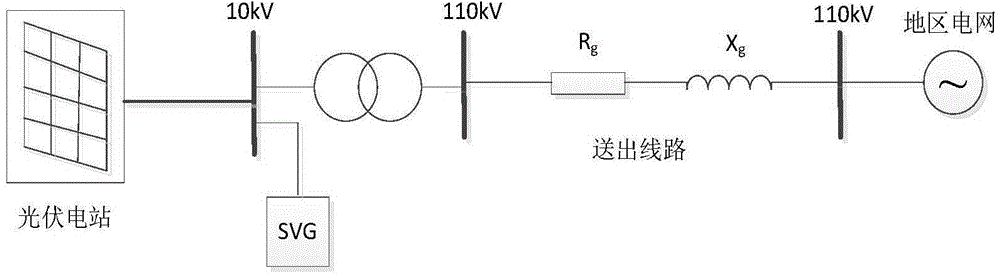
[0101] The total installed capacity of the photovoltaic power station is 60MW, and there are 4 collector lines in total. Each collector line is connected in series with 10 PVGUs. Each PVGU has a capacity of 1.5MW. It is stepped up to 10kV by a 0.29kV / 10kV step-up transformer to connect to the collector line. The distance between two adjacent groups of PVGUs is 1.2km, the capacity of the main transformer is 60MW, the length of the outgoing line is 80km, and the capacity of the SVG is -4Mvar-6Mvar. The grid-connected operation model of the photovoltaic power station is as follows: image 3 shown.

[0102] Light intensity S at the beginning ref =200W / m 2 , each photovoltaic power generation unit starts to work, and the light intensity suddenly increases to S at 1.5s ref =600W / m 2 , to 2.5s, the light intensity changes from S ref =600W / m 2 Burst to S ref =900W / m 2 .

[0103] Figure 4 (a)(b)(c) respectively represent the voltage change of the grid-connected point, the re...


PUM


Abstract

The invention discloses a large-scale photovoltaic power station reaction voltage control method. The control method comprises the following steps: detecting voltage at an integration point in real time, comparing the detected voltage with a reference value to automatically acquire and maintain reactive demanded quantity required for the voltage at the integration point through a PI controller, thereby realizing the dynamic regulation on the voltage at the integration point. According to the invention, the relation between the reactive power and the voltage is represented by using an analysis method of the sensitivity so as to provide the design process of the PI controller parameter, and the reactive power optimizing problem taking the uniform in-station voltage distribution as a target is translated into a non-linear planning model with a constraint condition and capable of fast and accurately solving; the reactive power reference quantity of each group of photovoltaic generating unit can be computed by solving the model so as to regulate the reactive power output of each photovoltaic generating unit in real time; on the basis of guaranteeing the stable voltage at the integration point, the in-station voltage distribution is improved, and the stable operation of the photovoltaic power station is guaranteed.

Description

technical field [0001] The invention belongs to the field of photovoltaic power station control, and in particular relates to a reactive power voltage control method of a large-scale photovoltaic power station. Background technique [0002] In recent years, the photovoltaic industry has developed rapidly. Due to the continuous reduction of system costs and the gradual maturity of photovoltaic grid-connected technology, the construction of large-scale grid-connected photovoltaic power plants is an effective way to utilize solar energy on a large scale. Different from distributed photovoltaic power generation, large-scale photovoltaic power plants are mostly built in desert areas, where the local load level is low, and the short-circuit capacity of the power grid in the connected area is small. A large amount of photovoltaic power needs to be sent out by high-voltage long-distance transmission lines. Since photovoltaic power generation is greatly affected by light, fluctuatio...

Claims


Application Information

Patent Timeline
Patent Type & Authority Applications(China)
IPC IPC(8): H02J3/16
CPCH02J3/16H02J3/383H02J3/50Y02E10/56Y02E40/10Y02E40/30
Inventor 周林邵念彬刘强郭珂杨明杜潇
Owner CHONGQING UNIV
Why Eureka
Try Eureka