Tool for machining workpieces

A technology of cutting processing and cutting parts, which is applied in the field of cutting tools and can solve problems such as time-consuming and complicated adjustment

Active Publication Date: 2015-05-27
MAPAL FABRIK FUER PRAEZISIONSWERKZEUGE (DE)
View PDF5 Cites 2 Cited by
  • Summary
  • Abstract
  • Description
  • Claims
  • Application Information

AI Technical Summary

Problems solved by technology

The disadvantage here is that with pivotable tool holders, the taper of at least one cutting edge changes when the tool machining diameter is adjusted
There are also toolholders with two adjusting wedges, but their adjustment is complicated and time-consuming

Method used


Image

  • Tool for machining workpieces
  • Tool for machining workpieces
  • Tool for machining workpieces

Examples


Embodiment Construction

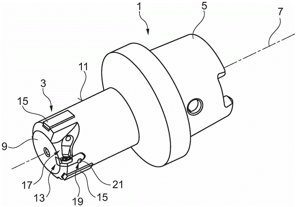
[0021] figure 1 A tool 1 is depicted, in particular a precision drilling tool, preferably a reamer. The tool 1 has a tool head 3 and a tool shank 5 , which here is designed in the form of a hollow rod and serves to fasten the tool 1 in a machine tool, a joint or an intermediate part or the like. Hollow rods and tool holders of the type shown here are known and will therefore not be described in detail here. Through the tool holder 5, torque is generally transmitted into the tool 1, so that the tool turns to machine the hole in the workpiece. The tool 1 is now pivoted about its center axis 7 .

[0022] The cutting head 3 has a body 9 with a peripheral surface 11 into which at least one cutting element 13 and at least one guide 15 are inserted. Usually, a plurality of such guide elements (also referred to as guide strips) are inserted into the body 9, which intercept the forces transmitted to the tool 1 by the cutting element 13 during the machining of the workpiece and guide...


PUM


Abstract

The invention relates to a reamer or similar tool, comprising a cutting device (13) having a cutting edge (23), a clamping device (17), by means of which the cutting device (13) can be clamped to the main body (9) of the tool (1), an adjusting device (55) that interacts with the cutting device (13), for adjusting the machining diameter of the tool (1), and a guiding device (19), which comprises an elongated guiding element (21), which interacts with an elongated guiding receptacle (39) in such a way that the cutting device (13) can be guided in a sliding manner perpendicularly to the center axis (7) during a displacement when the adjusting device (55) is activated. The guiding element (21) is provided on the cutting device and the guiding receptacle (39) is provided on the main body (9) of the tool (1) or the guiding element (21) is provided on the main body (9) of the tool (1) and the guiding receptacle (39) is provided on the cutting device (13). The guiding element (21) and the guiding receptacle (39) extend perpendicularly to the center axis (7) of the main body (9) of the tool (1). The tool (1) is characterized in that the guiding device (19) has a single guiding element (21) and / or a single guiding receptacle (39), and that the guiding element (21) has an elongated elevation and the guiding receptacle (39) has an elongated recess.

Description

technical field [0001] The invention relates to a tool for machining holes in workpieces according to the preamble of claim 1 . Background technique [0002] Tools of the type described herein are known, especially precision machining tools such as reamers and the like. When machining a hole in a workpiece, a relative rotational movement between the tool and the workpiece is effected to remove chips from the hole surface. Generally, the tool is rotated and displaced in the direction of its axis of rotation relative to the hole in the workpiece. The tool has at least one cutting edge of defined shape, a section of which, the main cutting edge, is inclined in the direction of feed movement. The secondary cutting edge adjoins the main cutting edge, which generally lowers counter to the direction of feed, whereby a taper is realized. When adjusting such a tool, it is not only necessary to calibrate the machining diameter of the tool, but also to calibrate the taper. It turns...

Claims


Application Information

Patent Timeline
IPC IPC(8): B23D77/04
CPCB23D77/044B23D2277/068B23B29/0341Y10T408/858Y10T407/227Y10T408/85995Y10T408/885B23C5/2472B23D77/04
Inventor 迪特尔·克雷斯
Owner MAPAL FABRIK FUER PRAEZISIONSWERKZEUGE (DE)
Why Eureka
Try Eureka