Vacuum resistive brazing method for lap piece

A resistance brazing and vacuum brazing furnace technology, which is used in welding equipment, metal processing equipment, manufacturing tools, etc., can solve the problem that the air cannot be discharged from the lap joint and the sheet brazing material, the quality of the brazing seam is reduced, and the small pores in the brazing seam can be solved. and other problems, to achieve the effect of excellent vacuum welding process method, uniform thickness of brazing layer and thermal stress distribution, and elimination of air conditions

Inactive Publication Date: 2015-06-03
XIANGTAN ELECTRIC MFG CORP LTD
View PDF9 Cites 15 Cited by
  • Summary
  • Abstract
  • Description
  • Claims
  • Application Information

AI Technical Summary

Problems solved by technology

In order to prevent oxides from being produced during the solder melting process, at present, sheet solder with flux components or directly using sheet solder without flux is generally used for resistance brazing. It is difficult for the sheet solder to be completely flat, so that part of the air between the lap joint and the sheet solder cannot be discharged, and finally exists in the brazing seam, resulting in small pores in the brazing seam or oxidation of the solder, which will reduce the brazing temperature. seam quality

Method used


Image

  • Vacuum resistive brazing method for lap piece

Examples


Embodiment 1

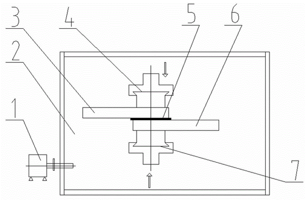
[0017] Embodiment 1, with reference to accompanying drawing, a kind of vacuum resistance brazing method of lap joint, the material of its lap joint is red copper, and it comprises the following steps:

[0018] Step 1. To clean the lap joints, remove the oil and oxides on the surface of the upper lap joint 3, the lower lap joint 6 and the solder 5 to ensure the cleanliness of the upper lap joint 3, the lower lap joint 6 and the solder 5 and dry;

[0019] Step 2, to fix the brazing material and the brazing material, use the upper electrode 4 and the lower electrode 7 to fix the brazing material 5 in the middle of the contact surface of the upper lapping part 3 and the lower lapping part 6;

[0020] Step 3: Vacuumize the brazing furnace, put the parts to be bonded with solder 5 into the vacuum brazing furnace 2, and use the compressor 1 to evacuate the vacuum brazing furnace 2 so that the vacuum degree in the vacuum brazing furnace 2 is 1.0×10 -2 Pa~1.0×10 -4 Pa;

[0021] Ste...

Embodiment 2

[0023] Embodiment 2, with reference to the accompanying drawings, a vacuum resistance brazing method for lap joints, the material of the lap joints is aluminum alloy, except that the vacuum degree in the vacuum brazing furnace 2 in step 3 is 1.0×10 -1 Pa~1.0×10 -3 Except Pa, all the other are consistent with embodiment 1.


PUM


Abstract

The invention relates to a vacuum resistive brazing method for a lap piece. The vacuum resistive brazing method comprises the following steps: 1, cleaning a to-be-lapped piece; 2, fixing brazing filler metal on the contact surface of the to-be-lapped piece by using upper and lower electrodes; 3, vacuumizing a brazing furnace, and putting the to-be-lapped piece fixed with the brazing filler metal into the vacuum brazing furnace, wherein the internal vacuum degree of the vacuum brazing furnace is 1.0*10<-1>-1.0*10<-4>Pa by vacuumizing; 4, heating the brazing filler metal until the temperature is higher than the welding point of the brazing filler metal by 30-80 DEG C; 5, cooling a resistive brazing piece, and discharging the resistive brazing piece from the furnace. The to-be-lapped piece to be resistively brazed is assembled and then is arranged in a vacuum environment, the influence on the to-be-lapped piece caused by air in the environment in the resistive brazing process is eliminated, and air conditions caused by air holes in the resistive brazing process are eliminated; meanwhile, the brazing surface is pollution-free in the welding process, and the welded brazing surface is pollution-free.

Description

technical field [0001] The invention relates to a vacuum resistance brazing method for lap joints. Background technique [0002] At present, the resistance brazing method of lap joints generally uses the upper and lower electrodes to fix the brazing material between the contact surfaces of the two lap joints, and after the workpiece is passed through a large current, it is placed between the two workpieces to be lapped. The solder between them is melted and welded together. In order to prevent oxides from being produced during the solder melting process, at present, sheet solder with flux components or directly using sheet solder without flux is generally used for resistance brazing. It is difficult for the sheet solder to be completely flat, so that part of the air between the lap joint and the sheet solder cannot be discharged, and finally exists in the brazing seam, resulting in small pores in the brazing seam or oxidation of the solder, which will reduce the brazing tem...

Claims


Application Information

Patent Timeline
Patent Type & Authority Applications(China)
IPC IPC(8): B23K1/008B23K1/20
CPCB23K1/008B23K1/206
Inventor 张越雷李再华徐勤文
Owner XIANGTAN ELECTRIC MFG CORP LTD
Why Eureka
Try Eureka