
Process for machining special winding gears for transformers with roll iron cores

A processing technology and transformer technology, applied in the field of winding gear processing technology for winding iron core transformers, can solve the problems of long installation time, low production efficiency, affecting coil winding, etc., and achieve long service life, convenient winding, Guaranteed hardness

Active Publication Date: 2015-06-03
广东华力通变压器有限公司
View PDF8 Cites 7 Cited by
  • Summary
  • Abstract
  • Description
  • Claims
  • Application Information

AI Technical Summary

Problems solved by technology

[0003] The disadvantage of this winding method is that the requirements for installing the positioning device are relatively high, and the concentricity of the positioning devices at both ends must be ensured to be high, otherwise the iron core will be easily rubbed during winding, resulting in the failure to complete the winding, so the installation time is longer
The second disadvantage is that if cardboard is used as the inner support of the winding, the friction of the core column is also prone to occur during winding. If there is a problem during winding, it cannot be returned and rewound, and the entire coil must be rewound.
Moreover, in the relatively humid environment in the south, the cardboard is easy to soften, causing the gears to fail to rotate, which will also affect the winding of the coil, and even cause the entire coil to be scrapped.
Therefore, the production efficiency of this method is not high, and problems are prone to occur in the winding process and cause waste.

Method used


Image

  • Process for machining special winding gears for transformers with roll iron cores
  • Process for machining special winding gears for transformers with roll iron cores
  • Process for machining special winding gears for transformers with roll iron cores

Examples


Embodiment Construction

[0027] In order to facilitate those of ordinary skill in the art to better understand the essence of the present invention, the specific implementation manners of the present invention will be described in detail below in conjunction with the accompanying drawings.

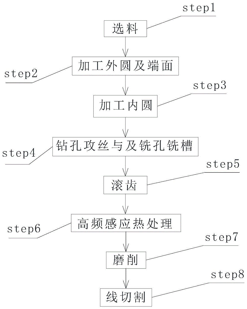
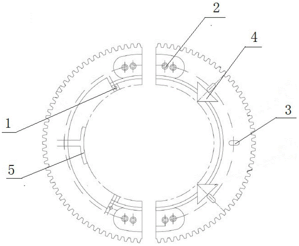
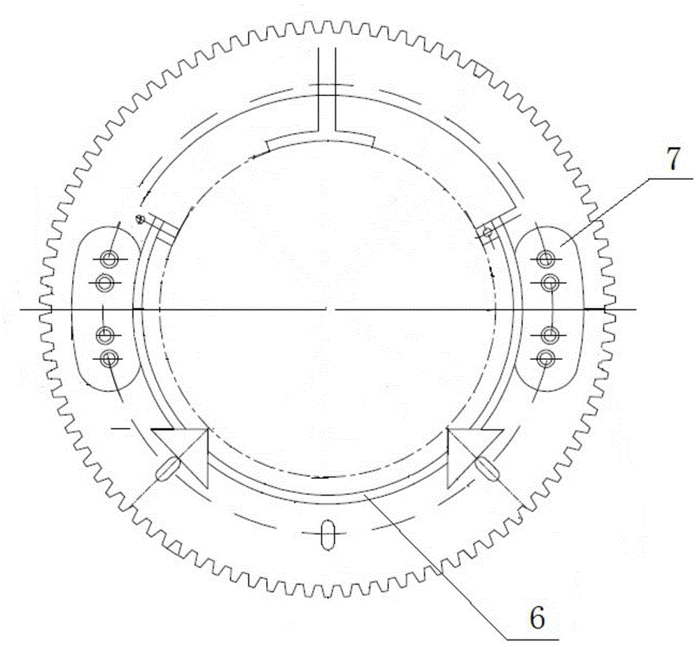
[0028] Such as Figure 1-Figure 3 As shown, a special winding gear processing technology for wound core transformers includes the following steps:

[0029] The first step step1 is material selection. Firstly, No. 45 steel is selected as the workpiece to be processed according to the part requirements, in preparation for the subsequent process. Then determine the positioning center to ensure that the size meets the requirements of the workpiece; finally drill a fixing hole in the positioning center to fix the workpiece when processing it later.

[0030] The second step step2 is to process the outer circle and end face, and rough the outer circle of the workpiece on the lathe to remove the excess margin of the blan...


PUM


Abstract

The invention discloses a process for machining special winding gears for transformers with roll iron cores. The process includes steps of selecting materials; machining outer circles and end surfaces; machining inner circles; drilling holes, tapping threads and milling the holes and grooves; hobbing gears; carrying out high-frequency induction heat treatment on the gears; grinding the gears; linearly cutting the gears; positioning, clamping and machining the gears, and the like. The process for machining the special winding gears for the transformers with the roll iron cores has the advantages that positioning triangles are arranged on workpieces, each workpiece is cut into halves, and accordingly the special winding gears and frameworks of winding machines can be conveniently mounted and conveniently assembled; T-shaped bosses are arranged on the workpieces by means of machining, low-voltage line holes and oblong slotted holes are formed in the workpieces by means of machining, and accordingly winding can be facilitated to a great extent; the integral workpieces are made of number-45 steel, high-frequency induction heat treatment and grinding treatment are combined with each other, accordingly, the hardness, the abrasion resistance and the precision of the integral gears can be guaranteed, and the gears are long in service life.

Description

technical field [0001] The invention relates to the field of processing winding devices for wound iron core transformers, in particular to a processing technology for winding gears specially used for wound iron core transformers. Background technique [0002] One of the key technologies of wound core transformers is how to conveniently and quickly wind coils on closed three-dimensional wound core transformers. The existing three-dimensional wound core transformer coil winding technology is to install a positioning device with a winding gear on the core column of the three-dimensional wound core, and then place cardboard or epoxy cloth board on the edge of the gear. [0003] The disadvantage of this winding method is that the installation of the positioning device is relatively high, and the concentricity of the positioning devices at both ends must be ensured to be high, otherwise the iron core will be easily rubbed during winding, resulting in the failure to complete the wi...

Claims


Application Information

Patent Timeline
IPC IPC(8): B23P15/14
CPCB23P15/14
Inventor 欧伟洪
Owner 广东华力通变压器有限公司
Learn More