separation tube

A separation tube and centrifuge tube technology, which is used in medical and high-risk areas where a large number of cell samples are separated

Inactive Publication Date: 2016-09-14
李小阁
View PDF5 Cites 0 Cited by
  • Summary
  • Abstract
  • Description
  • Claims
  • Application Information

AI Technical Summary

Problems solved by technology

[0019] The invention provides a separation tube, which can overcome the existing problems and defects of existing products, has wider application, more convenient operation, safer product and high cell yield

Method used


Image

  • separation tube
  • separation tube
  • separation tube

Examples


Embodiment 2

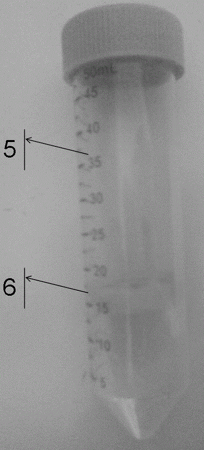
[0044] 1. Take a 50ml sterile centrifuge tube and add 15ml of human peripheral blood lymphocyte separation medium;

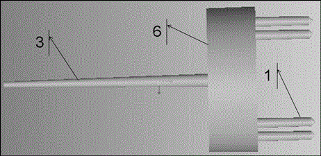
[0045] 2. Insert a Type 2 spacer (eg figure 1 As shown, the top corner is upward, the length of the leg is 20mm, and there is no blind hole);

[0046] 3. Add 1ml blood sample to the separation tube;

[0047] 4. Centrifuge, set the centrifugal force to 800 to 1000g, and the time to 20min to 30min;

[0048] 5. Pour out the sample above the partition;

[0049]6. Add about 20ml of normal saline to wash, and centrifuge to remove the supernatant;

[0050] 7. Add about 25ml of normal saline, mix well, take samples and count.

[0051] After this embodiment, after the centrifugation, the separator drops from the 15ml scale line to the 12ml scale line, the separator is firmly stuck on the centrifuge tube, the separator will not float up, the upper layer of the separator is poured out, and the separated lymphocytes are recovered The rate can reach more than 95%, and t...


PUM

PropertyMeasurementUnit
lengthaaaaaaaaaa
recovery rateaaaaaaaaaa

Abstract

The invention discloses a separation tube device and an application method thereof. The separation tube device comprises a centrifuge tube and a partition. The partition is put in the centrifuge tube before being used, can separate conventional specimens and also can separate small-size specimens. Compared with the traditional separation tube, the separation tube device is easy to clean and less in chemical residue, can reduce the influence of material dissolution and separation liquid on separated cells, and can be widely applied to medical diagnosis, biological treatment and scientific research work.

Description

technical field [0001] The invention relates to a separator-type separation tube, which is mainly used in the field of biology, and is suitable for the separation of human and animal cells such as lymphocytes, white blood cells, and stem cells, and is especially suitable for high-risk medical technologies such as cell therapy and the separation of a large number of cell samples. field. Background technique [0002] Cell separation is one of the most commonly used separation methods in the fields of biology and medicine. It is often used in the performance research of specific cells, expanded culture, disease diagnosis and disease treatment. In particular, immune cell therapy technology has developed rapidly in recent years and has been widely used clinically. [0003] As early as 1992, biological cell immunotherapy was widely used clinically in the United States, and was officially approved by the US FDA. [0004] In March 2009, the Ministry of Health promulgated the "Admi...

Claims


Application Information

Patent Timeline
Patent Type & Authority Patents(China)
IPC IPC(8): C12M1/24C12M1/00
Inventor 李小阁
Owner 李小阁
Why Eureka
Try Eureka