
Head installation structure of a template sewing machine

An installation structure and technology for sewing machines, applied in the field of sewing machines, can solve problems such as vibration and noise of worktables and racks, and achieve the effects of improving sewing accuracy and reducing vibration and noise.

Active Publication Date: 2017-11-07
浙江耐拓机电科技有限公司
View PDF5 Cites 0 Cited by
  • Summary
  • Abstract
  • Description
  • Claims
  • Application Information

AI Technical Summary

Problems solved by technology

[0004] The frames of existing template sewing machines are all rigid structures, and the machine head is directly fixed on the worktable or the frame. During the processing of the template sewing machine, the vibration of the machine head is directly transmitted to the worktable or the frame, causing Noise from tabletop and rack vibrations

Method used


Image

  • Head installation structure of a template sewing machine
  • Head installation structure of a template sewing machine
  • Head installation structure of a template sewing machine

Examples


Embodiment 1

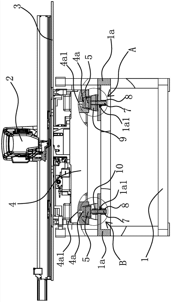
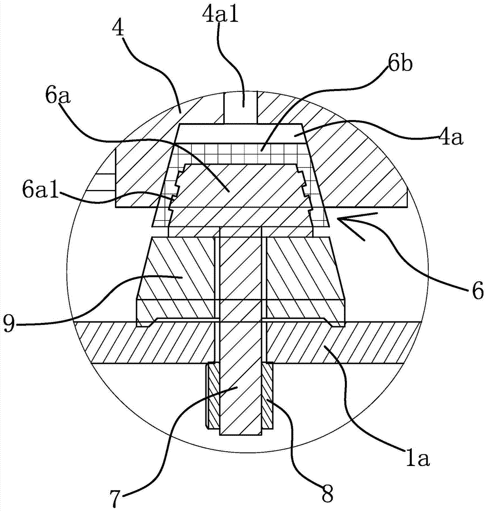
[0025] The template sewing machine includes a frame 1 , a machine head 2 and a worktable 3 , and the worktable 3 is arranged on the frame 1 . The head installation structure of the template sewing machine includes a base 4, a positioning hole 4a, a support portion 1a, a relief hole 1a1, a support pad 5, a head 6, a stud 7 and a lock nut 8.

[0026] Specifically, as figure 1 and Figure 4 As shown, there is an accommodating space inside the middle position of the frame 1 , the base 4 is located in the accommodating space, and the support portion 1 a of the frame 1 is located below the base 4 . In actual production and manufacturing, the support part 1a can also be fixed on the frame 1 by using a separate component. The machine head 2 is fixed on the base 4 , and the machine head 2 protrudes from the upper surface of the worktable 3 .

[0027] Such as figure 1 and figure 2 As shown, several supporting pads 5 are arranged between the base 4 and the supporting part 1a. In th...

Embodiment 2

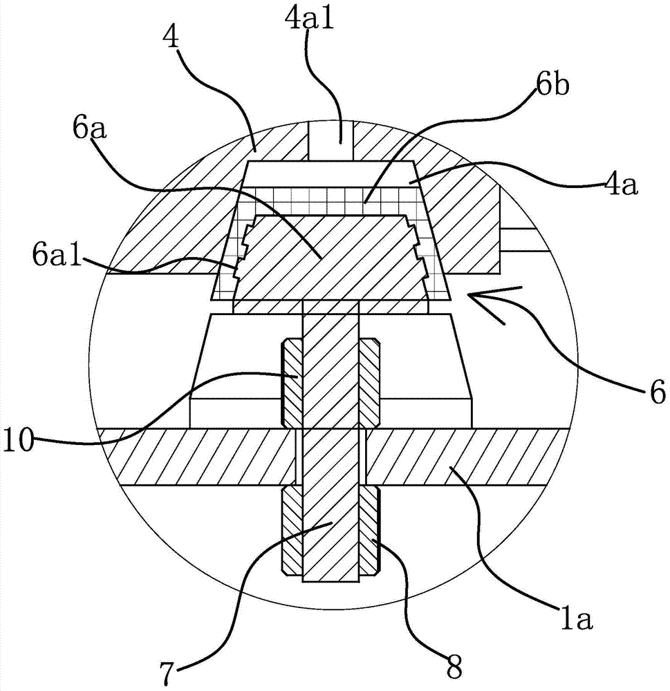
[0032]The technical solution in this embodiment is basically the same as the technical solution in Embodiment 1, the difference is that in this embodiment, a positioning block 9 is arranged between each supporting pad 5 and the supporting part 1a, and the positioning The blocks 9 are in rigid contact with the supporting pads 5 , and the studs 7 of each of the supporting pads 5 respectively pass through the corresponding relief holes 1a1 and are threadedly connected with locking nuts 8 . The function of setting the positioning block 9 is to keep the base 4 level by adjusting the height of the positioning block 9 , thereby ensuring the position accuracy of the machine head 2 relative to the worktable 3 .

Embodiment 3

[0034] The technical solution in this embodiment is basically the same as the technical solution in Embodiment 1, the difference is that in this embodiment, the support pad 5 is made of metal material, and the positioning hole 4a is provided with a shape of the inner wall of the positioning hole 4a Matching rubber gaskets. After the rubber gasket is damaged or fails, it is more convenient to replace.


PUM


Abstract

The invention provides a head mounting structure for a template sewing machine, and belongs to the technical field of sewing machines. The problem of noise produced by the vibration of a working bedplate and a rack of a conventional template sewing machine is solved. The head mounting structure for the template sewing machine comprises a base in a rack, wherein a head is fixedly arranged on the base, and extends from the upper surface of a working bedplate; a support part positioned below the base is arranged on the rack; a plurality of support cushion blocks are arranged between the base and the support part; each support cushion block is positioned on the support part, and elastically contacts with the base. According to the head mounting structure for the template sewing machine, the head is fixedly arranged on the base, and then the base is arranged on the rack through the support cushion blocks to realize floating connection between the head and the rack, so that the working bedplate of the template sewing machine is more stable in a machining process, and the sewing accuracy of the template sewing machine is improved.

Description

technical field [0001] The invention belongs to the technical field of sewing machines, and relates to a template sewing machine, in particular to a head mounting structure of the template sewing machine. Background technique [0002] Garment template is based on the combination of garment process engineering, mechanical engineering and CAD digitization principles, by slotting the mold material and using a template sewing machine to realize sewing according to the mold trajectory. [0003] Template sewing machine refers to the sewing equipment for practical application in combination with garment template technology. For example, a template sewing machine disclosed in Chinese patent [application number 201420235732.4; authorized announcement number CN203977090U] includes a frame, a sewing machine head, a template conveying base and a template moving frame; the template conveying base is located below the worktable, and the template conveying base is fixedly connected with th...

Claims


Application Information

Patent Timeline
Patent Type & Authority Patents(China)
IPC IPC(8): D05B75/04
Inventor 张春木洪鹏苏伟国
Owner 浙江耐拓机电科技有限公司
Learn More