Machine vision illumination light source and operating method of machine vision illumination light source

A lighting source and machine vision technology, applied in the direction of light source, electric light source, lighting device, etc., can solve the problems of poor image acquisition effect, inability to change the light source, and poor image quality, so as to increase the uniformity of illumination and improve the detection efficiency , the effect of convenient operation

Active Publication Date: 2015-06-03
GUANGDONG UNIV OF TECH
View PDF4 Cites 7 Cited by
  • Summary
  • Abstract
  • Description
  • Claims
  • Application Information

AI Technical Summary

Problems solved by technology

If the angle of the light source cannot be changed and kept consistent, the light will be uneven and the quality of the captured image will be poor
[0004] Chinese patent CN201210497326.0 discloses a machine vision LED lighting source. This technical solution is provided with a diffuser plate on the irradiation surface of the LED matrix light source. In this case, richer brightness and incident angle can be obtained, and the light is uniform, but this technical solution cannot change the angle of the light source and keep the angle consistent, resulting in poor image acquisition effect

Method used


Image

  • Machine vision illumination light source and operating method of machine vision illumination light source
  • Machine vision illumination light source and operating method of machine vision illumination light source
  • Machine vision illumination light source and operating method of machine vision illumination light source

Examples


Embodiment 1

[0041] Such as Figure 1-2 As shown, it is a structural schematic diagram of the machine vision lighting source of the present invention, including a base plate 4, a housing 18 fitted with the base plate 4, and a transmission component installed on the base plate, and the transmission component includes a rotating part 100 and a transmission part 200.

[0042] Wherein, the rotating part 100 includes a knob 1, and a bearing 2 and a large helical gear 3 are sequentially arranged under the knob 1, and the large helical gear 3 cooperates with the bearing 2; wherein, the transmission part 200 includes a small helical gear 5, and the small helical gear 5 is connected to the The large helical gear 3 is meshed with the small helical gear 5. A screw 6 is installed on the screw 6. A slider 8 is installed on the screw 6. Each slider 8 is connected with four pulleys 9 by screws 10. The slider 8 Installed in cooperation with the slide rail 7 , the slide block 8 is connected with th...

Embodiment 2

[0047] This embodiment is a machine vision lighting source, which specifically includes the following steps:

[0048] S1. Fix the machine vision lighting source of the present invention on the image acquisition end of the machine vision detection system, so that the axis of the camera is aligned with the center opening of the light source;

[0049] S2. Adjust the camera and the machine vision lighting source of the present invention to the height of the detection range by adjusting the mechanical mechanism of the detection system;

[0050] S3, turn on the power supply, the machine vision lighting source of the present invention works;

[0051] S4. Obtain the required inclination angle of the LED module according to the detected height, and then rotate the knob of the light source to obtain the required inclination angle of the LED module. The camera starts to work and collects images.

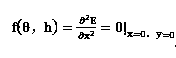
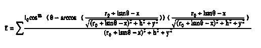
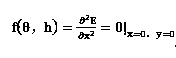
[0052]Wherein, the inclination angle required by the LED module is obtained in the step S4...


PUM


Abstract

The invention discloses a machine vision illumination light source, comprising a base plate, and a shell which is arranged in a manner of fitting with the base plate, wherein a driving component is arranged on the base plate; the driving component comprises a rotating part and a driving part; the rotating part comprises a knob; a bearing and a large bevel gear are sequentially arranged below the knob; the driving part comprises a small bevel gear; the small bevel gear is meshed with the large bevel gear; the small bevel gear is provided with a lead screw; the lead screw is provided with a sliding block; the sliding block is arranged in a manner of fitting with a sliding rail; the sliding block is connected with an LED (light emitting diode) module through a connecting rod; the LED module is positioned below the base plate. Meanwhile, the invention further discloses an operating method of the machine vision illumination light source. According to the machine vision illumination light source and the operating method of the machine vision illumination light source, an angle of the LED module can be adjusted through linkage by means of rotating the knob, and the consistence is kept; for different detection characteristics, the uniform illumination can be also realized under the condition of changing the direction of incident light, and the operation is convenient.

Description

technical field [0001] The invention relates to the field of photoelectric lighting, in particular to a machine vision lighting source and an operating method thereof. Background technique [0002] Machine vision is to use machines to replace our human eyes for detection and judgment. Traditional manual detection not only requires a lot of manpower but also is inefficient. Machine vision is often used for product quality inspection in the mass production process, especially in situations where the detection environment is dangerous and human vision is difficult to satisfy. Machine vision can greatly improve detection accuracy and detection speed, thereby improving production efficiency and avoiding deviations and errors caused by human visual inspection. Users in the market have higher and higher requirements for product quality and quality control. In this case, in order to improve the quality and competitiveness of products, machine vision will be a major trend. [00...

Claims


Application Information

Patent Timeline
Patent Type & Authority Applications(China)
IPC IPC(8): F21S8/00F21V14/02F21Y101/02
CPCF21S8/00F21V14/02
Inventor 陈新度林家平陈新王晗王素娟高健杨志军吴磊骆伟岸罗迪
Owner GUANGDONG UNIV OF TECH
Why Eureka
Try Eureka