Lighting Components and Surgical Lights

A technology for lighting components and lighting units, applied in the field of lighting, can solve problems such as low light collection efficiency

Active Publication Date: 2017-01-04
SHENZHEN COMEN MEDICAL INSTR +1
View PDF8 Cites 2 Cited by
  • Summary
  • Abstract
  • Description
  • Claims
  • Application Information

AI Technical Summary

Problems solved by technology

For a TIR lens with a general thickness of 20mm, the optical path on the side of the lens exceeds 20mm. Even if the optical path is 20mm, the side transmittance of the TIR lens drops to about 61.6% for PMMA, 46% for PC, and 57.4% for E48R, while the TIR lens The thickness of the middle part generally exceeds 10mm. Even if the optical path is 10mm, the central light transmittance of the TIR lens drops to about 78.5% for PMMA, 67.8% for PC, and 75.7% for E48R; usually, the energy in the central part of the TIR lens accounts for about 55% of the total energy. , the side part accounts for about 45% of the total energy, so the total light transmittance of the TIR lens drops to about 70.9% for PMMA, 58% for PC, and 67.5% for E48R, resulting in low light collection efficiency

Method used


Image

  • Lighting Components and Surgical Lights
  • Lighting Components and Surgical Lights
  • Lighting Components and Surgical Lights

Examples


Embodiment 1

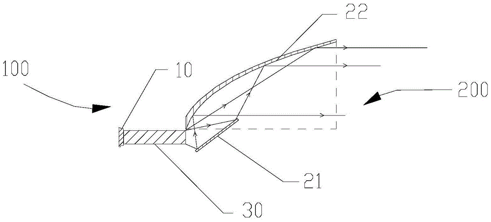
[0046] like figure 1 As shown, a lighting assembly includes a lighting unit 100 and a reflective cup 200. The lighting unit 100 includes a light source 10. The reflective cup 200 has an incident end and an outgoing end. The incident end of the reflective cup 200 is an end that receives light from the light source. The exit end of the light source is the end that emits the light from the light source. The lighting unit 100 is located on one side of the incident end of the reflective cup 200 . The reflective cup 200 includes a first reflective element 21 and a second reflective element 22 . The first reflective element 21 has a reflective surface, the reflective surface of the first reflective element 21 is a plane, the surface of which can be coated with a reflective film, specifically, the first reflective element 21 is a plane reflective mirror. The second reflective element 22 also has a reflective surface. The reflective surface of the second reflective element 22 is a s...

Embodiment 2

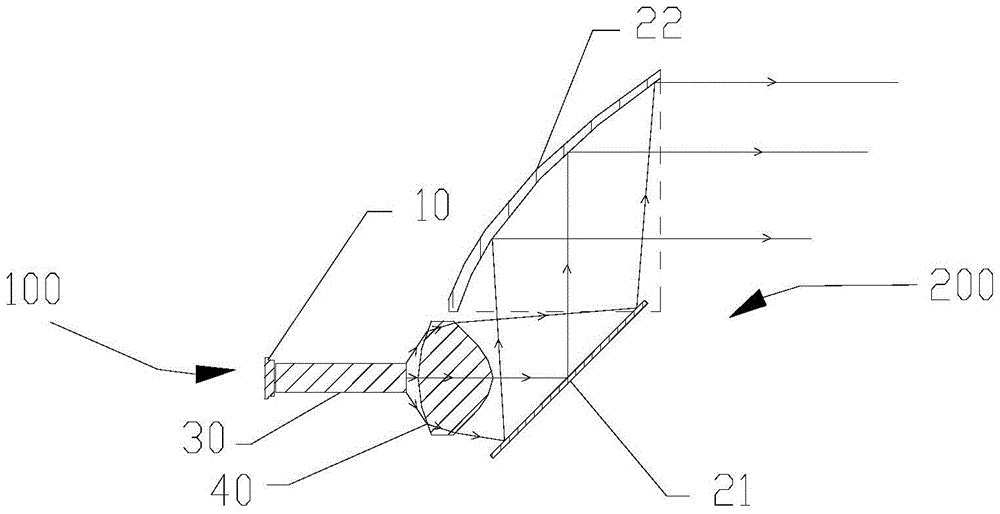
[0058] like Figure 2A and Figure 2B As shown, on the basis of Embodiment 1, the lighting unit 100 may further include a first lens 40 . When the first light mixing integrating rod 30 is omitted, the first lens 40 is located between the light source 10 and the incident end of the reflector cup 20, and when the first light mixing integrating rod 30 is used, the first lens 40 is located at the first light mixing integrating rod 30 and the incident end of the reflective cup 20. The first lens 40 uses a positive lens, preferably a positive lens made of a cold-processed glass material. The positive lens has a converging effect, and the divergent light emitted directly from the light source 10 or the first mixing rod 30 passes through the first lens 40 Convergence, the light angle is converged to Left and right, the angle has been relatively reduced, and further, the lighting unit 100 has a virtual light source symmetrically with respect to the first reflective element 21. 21 ...

Embodiment 3

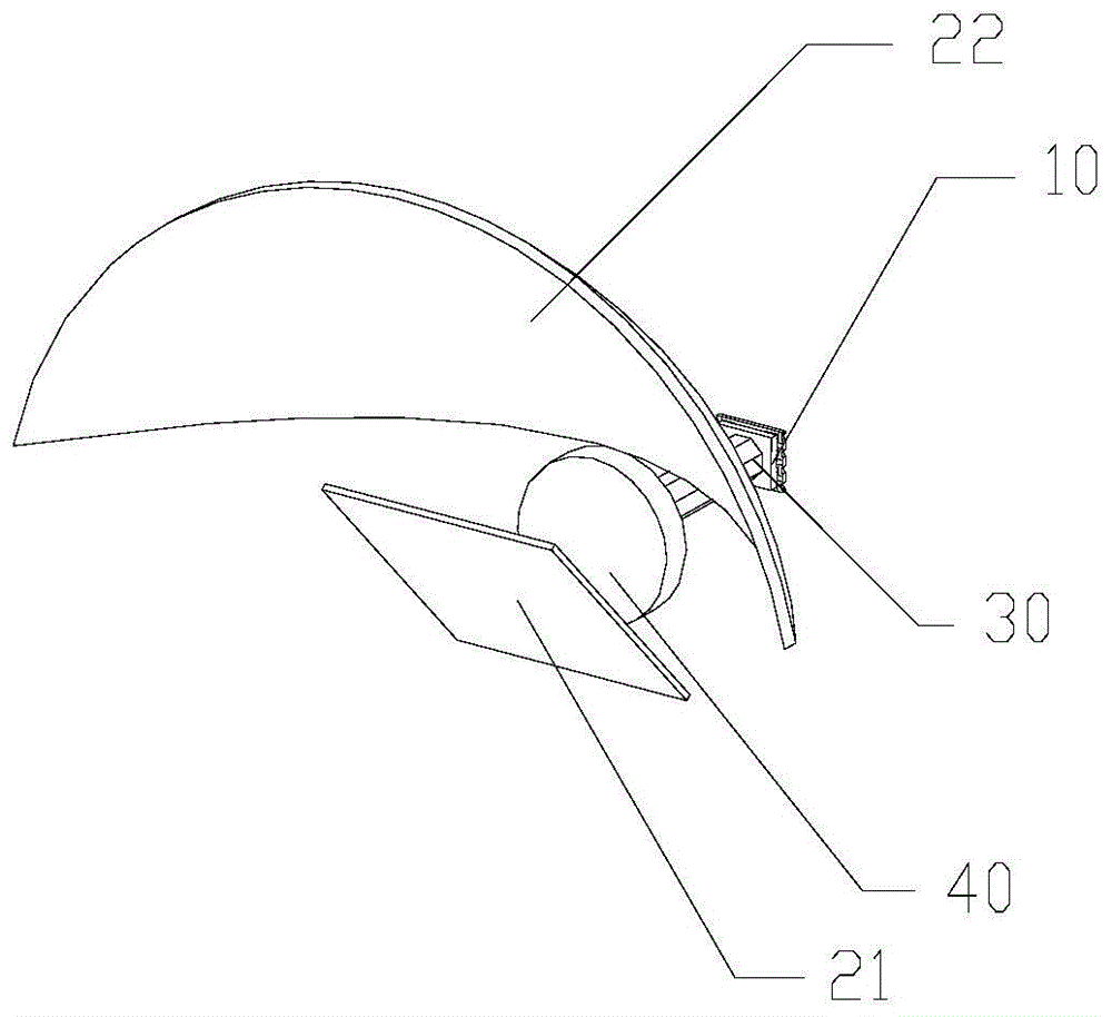
[0062] like image 3 As shown, on the basis of Embodiment 1, the lighting assembly further includes a first reflector 60 , if the first integrating rod 30 is omitted, the first reflector 60 is located between the light source 10 and the reflector 20 . If the first light mixing rod integrator 30 is used, the first reflection part 60 is located between the first light mixing rod integrator 30 and the incident end of the reflective cup 200 .

[0063] The end of the first reflection part 60 close to the light source is the incident end, and the end close to the reflective cup is the exit end. The first reflector 60 can be cylindrical or conical, and a through hole is provided in the first reflector 60. The through hole is in the shape of a conical truncated hole. The diameter of the aperture gradually increases from the incident end to the exit end, and the through hole of the first reflection part 60 is coated with a reflection mold to form a reflection surface, and the inclinat...


PUM


Abstract

The invention relates to a lighting component. The lighting component comprises a lighting unit and a reflecting cup, wherein the reflecting cup is provided with an incident end and an emergent end; the lighting unit is positioned at one side of the incident end of the reflecting cup; the lighting unit comprises a light source, and the reflecting cup comprises a first reflecting element and a second reflecting element, and the reflecting surface of the first reflecting element is a plane or an ellipsoid; the reflecting surface of the second reflecting element is a semi-paraboloid, one of the reflecting surface of the first reflecting element and the reflecting surface of the second reflecting element faces the lighting unit, and the other faces an illuminating area; the light of the light source is reflected to the second reflecting element via the first reflecting element, and the light is collimated by the second reflecting element to be small-angle light; or the light of the light source is collimated by the second reflecting element to enter the first reflecting element, the angle of the light is deflected to the horizontal direction by the first reflecting element; the lighting component collimates the angle of the light through the reflection of the reflecting cup, so that the influence caused by material absorption is avoided, the energy loss is not caused, and the light collection efficiency is high.

Description

technical field [0001] The invention relates to the technical field of illumination, in particular to an illumination assembly and an operating lamp. Background technique [0002] The light required by the surgical lamp is a small-angle light. Usually, the light directly emitted by the LED light source is ±90 degrees and has a Lambertian distribution. In order to collimate the light directly emitted by the LED to a small-angle light, the following methods are usually used: [0003] 1. Use reflective cups, such as Figure 13 As shown, if the light emitted by the light source 300 has an emission angle greater than φ, the reflective cup 400 will produce a reflection effect to achieve the effect of collimating the light to a small angle; but if the emission angle is smaller than φ, the light will directly exit. Scattered. The lost energy accounts for about 40% of the total energy, and the light collection efficiency is low. [0004] 2. Using TIR lens, using the convergence eff...

Claims


Application Information

Patent Timeline
Patent Type & Authority Patents(China)
IPC IPC(8): F21V7/09F21V7/22F21V9/08F21W131/205F21Y115/10
CPCF21V7/09F21V7/22F21V9/40F21W2107/10F21W2131/205
Inventor 封志纯封云
Owner SHENZHEN COMEN MEDICAL INSTR
Why Eureka
Try Eureka