Drum type feeding device for garbage incinerator of circulating fluidized bed and feeding method

A waste incinerator and circulating fluidized bed technology, which is applied in the combustion method, incinerator, combustion type, etc., can solve the problems of hardening, insufficient combustion, and high cost of exhaust gas treatment, and achieves low flue gas volume and sufficient waste combustion. Effect

Active Publication Date: 2015-06-03
银川中科环保电力有限公司
View PDF7 Cites 3 Cited by
  • Summary
  • Abstract
  • Description
  • Claims
  • Application Information

AI Technical Summary

Problems solved by technology

[0003] The invention provides a drum-type feeding device and feeding method for a circulating fluidized bed garbage incinerator in which the density of garbage increases in a small amount as the feeding distance increases so that the garbage can enter the incinerator in a loose state. Solved the problems of incomplete combustion and high cost of exhaust gas treatment caused by hardening phenomenon caused by the existing feeding device

Method used


Image

  • Drum type feeding device for garbage incinerator of circulating fluidized bed and feeding method
  • Drum type feeding device for garbage incinerator of circulating fluidized bed and feeding method
  • Drum type feeding device for garbage incinerator of circulating fluidized bed and feeding method

Examples


Embodiment 1

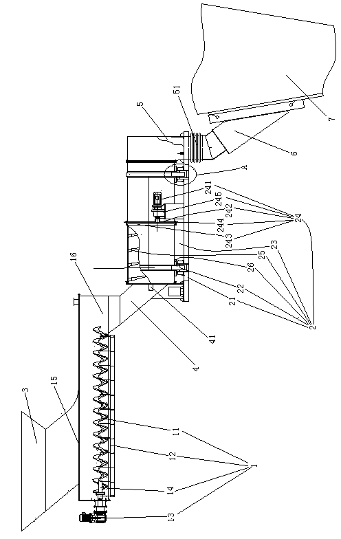
[0024] Embodiment one, see figure 1 A drum-type feeding device for a circulating fluidized bed garbage incinerator includes a primary feeder 1 and a secondary feeder 2 . The primary feeder 1 is located above the axial left end of the secondary feeder 2 .

[0025] The primary feeder 1 is set horizontally. The primary feeder 1 includes a screw feed blade 11 , a shell 12 of the primary feeder and a driving motor 13 of the primary feeder. There are two screw feed blades 11. Two screw feeding blades 11 are located in the same horizontal plane and arranged in parallel. Two screw feeding blades 11 are distributed along the front and rear direction (in the figure because the screw feeding blade at the rear is blocked by the screw feeding blade in front, so only one screw feeding blade can be seen). The screw feed vane 11 is located in the shell 12 of the primary feeder. Each screw feeding blade 11 is connected with a primary feeder drive motor 13 through a primary feeder drive sh...

Embodiment 2

[0034] Embodiment two, see Figure 4 , the difference from the first embodiment is: it also includes a suspension frame 9 and a coating heating mechanism 8 . Suspension frame 9 and coating type heating mechanism 8 each have two.

[0035] The feed hopper 3 is only supported on the primary feeder 1 by the hanger 9 . The suspension frame 9 includes a connecting rod 91 and five shock absorbing rods 92 . The connecting rod 91 is an arc-shaped structure that arches downward (certainly upward is also possible). The five damping rods 92 are a horizontal damping rod 921 , two longitudinal damping rods 922 and two vertical damping rods 923 . One end of the connecting rod 91 is connected with the feed hopper 3 . The other end of the connecting rod 91 is connected with one end of the horizontal damping rod 921 . The other end of the horizontal damping rod 921 is connected with one end of the two longitudinal damping rods 922 . One ends of the two vertical shock absorbing rods 923 ar...


PUM


Abstract

The invention relates to the field of garbage incineration disposal, in particular to a drum type feeding device for a garbage incinerator of a circulating fluidized bed. The drum type feeding device for the garbage incinerator of the circulating fluidized bed comprises a primary feeding machine and a secondary feeding machine, wherein the primary feeding machine is connected with the secondary feeding machine through a seal leg; the primary feeding machine is positioned above the secondary feeding machine; the secondary feeding machine comprises a supporting roller, a feeding drum and a driving mechanism for driving the feeding drum to rotate; the feeding drum is supported on the supporting roller under the condition that a peripheral surface of the feeding drum is in contact to the supporting roller; the feeding end of the feeding drum is rotatably and hermetically connected with the seal leg; a plurality of spiral guide blades are arranged in the feeding drum; the radial outer ends of the spiral guide blades are fixedly connected with an inner peripheral surface of the feeding drum; and feeding space is surrounded by radial inner ends of the spiral guide blades. The drum type feeding device for the garbage incinerator of the circulating fluidized bed has the advantages that the increasing amount of the compactness of garbage is reduced along with increasing of a feeding distance, and the garbage can enter the incinerator in a loose state. The problems that materials are hardened during conveying of the existing feeding device, combustion is insufficient, and tail gas treatment cost is high are solved.

Description

technical field [0001] The invention relates to the field of garbage incineration treatment, in particular to a drum-type feeding device and a feeding method for a circulating fluidized bed garbage incinerator. Background technique [0002] The feeding device of the initial circulating fluidized bed garbage incinerator is a negative pressure feeding method, that is, to control the furnace pressure or increase the elevation of the feeding port, so that the area where the garbage enters the furnace is a negative pressure area, so as to avoid the high-temperature flue gas from the furnace. into the feeding device to cause fire and leakage and pollute the environment. There are single-stage feeding method through the first-stage screw feeder and two-stage feeding method through the second-stage screw feeder. A feeding device with two-stage feeding method is disclosed in the patent document with the Chinese patent number 2007201819504, the authorized announcement date being Augu...

Claims


Application Information

Patent Timeline
Patent Type & Authority Applications(China)
IPC IPC(8): F23G5/44
CPCF23G5/444F23G2205/12
Inventor 方旭东王武忠姜志红方朝军杨雷远叶俊
Owner 银川中科环保电力有限公司
Why Eureka
Try Eureka