Method and system for monitoring transmission line impulse electrostatic discharge test response

An electrostatic discharge test, transmission line pulse technology, applied in the direction of testing dielectric strength, etc., can solve problems such as many test steps, inability to locate damage points, difficult to achieve accurate device positioning, etc., to achieve full use of test information and good engineering application value. , the effect of good technical support

Active Publication Date: 2017-06-16
FIFTH ELECTRONICS RES INST OF MINIST OF IND & INFORMATION TECH
View PDF5 Cites 0 Cited by
  • Summary
  • Abstract
  • Description
  • Claims
  • Application Information

AI Technical Summary

Problems solved by technology

However, damage to electronic components caused by electrostatic discharge tests may have various degrees of burnout
When the degree of burn is relatively small and the burn area is small, the burn phenomenon cannot be observed by optical microscope or scanning electron microscope, so the damage point location cannot be realized
When the burnt degree is serious and the burnt area is large, it is difficult to accurately locate the initial damage position of the device by optical microscope or scanning electron microscope observation
In addition, the existing technical solutions also have shortcomings such as many test steps, long test time, and insufficient use of test information.

Method used


Image

  • Method and system for monitoring transmission line impulse electrostatic discharge test response
  • Method and system for monitoring transmission line impulse electrostatic discharge test response

Examples


Embodiment Construction

[0018] The specific implementation of the method for monitoring transmission line pulse electrostatic discharge test response of the present invention will be described in detail below in conjunction with the accompanying drawings.

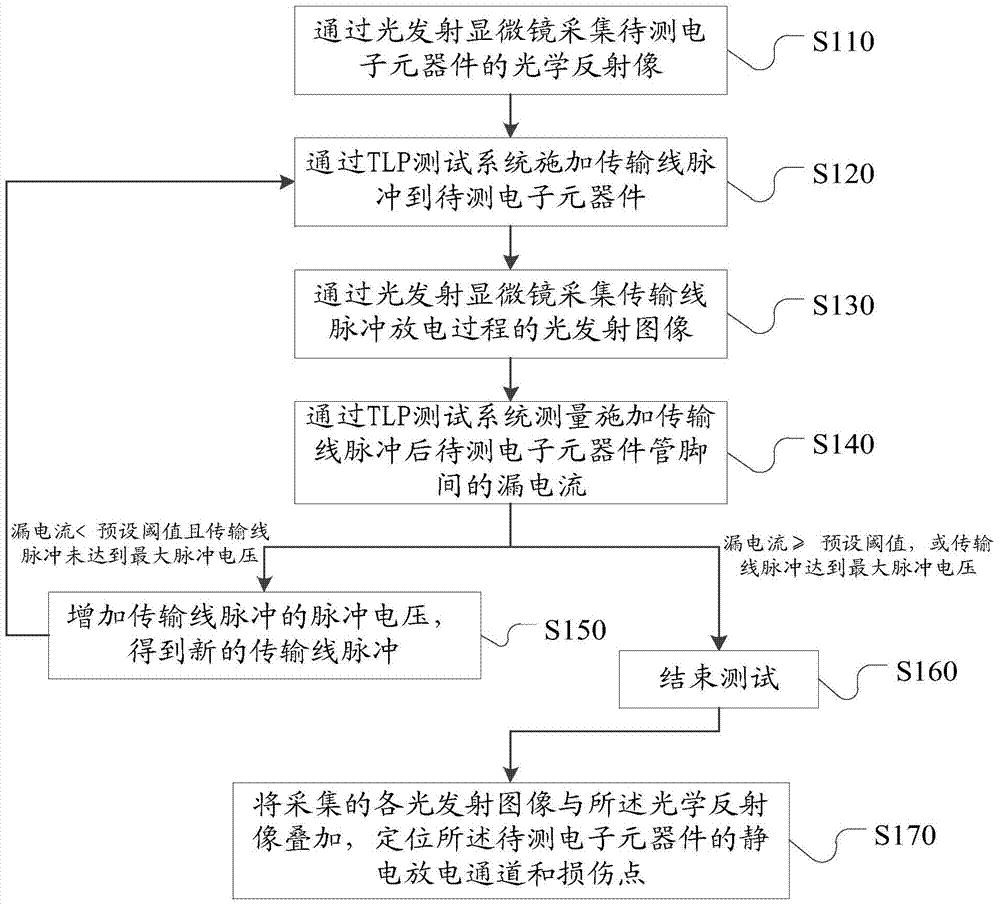
[0019] Such as figure 1 As shown, a method for monitoring the response of a transmission line pulse electrostatic discharge test, comprising steps:

[0020] S110, collecting an optical reflection image of the electronic component to be tested through a light emission microscope;

[0021] S120, applying a transmission line pulse to the electronic component to be tested through the TLP testing system;

[0022] S130. Collect a light emission image of the transmission line pulse discharge process through a light emission microscope;

[0023] S140. Using the TLP test system to measure the leakage current between the pins of the electronic component to be tested after the transmission line pulse is applied, if the leakage current is less than a preset...


PUM


Abstract

The invention relates to a method and a system for monitoring the pulse electrostatic discharge test response of a transmission line. When the TLP test system applies transmission line pulses of different pulse voltages to electronic components, a light emission microscope collects the light emission images of the pulse discharge process of each transmission line, Therefore, at the end of the test, each light emission image and the optical reflection image are superimposed to precisely locate the electrostatic discharge channel and damage point of the electronic components. The invention realizes the real-time monitoring of the electroluminescence phenomenon during the pulse electrostatic discharge test of the transmission line, which is convenient for clarifying the electrostatic discharge channel inside the electronic components during the electrostatic discharge test, timely discovering and accurately locating the damage point of the electrostatic discharge, so as to determine the product Antistatic weak link. In addition, the test information of the present invention is fully utilized, and the test steps are simple, which can provide good technical support for electrostatic damage research of electronic components and ESD design improvement, and has good engineering application value.

Description

technical field [0001] The invention relates to the technical field of electrostatic discharge testing of electronic components, in particular to a method for monitoring the response of a transmission line pulse electrostatic discharge test and a system for monitoring the response of a transmission line pulse electrostatic discharge test. Background technique [0002] Transmission Line Pulse (TLP) test refers to the use of transmission lines to generate short pulses (50 nanoseconds to 200 nanoseconds) to measure the current / voltage of ESD (Electro-Static discharge, electrostatic discharge) protection structures in electronic components characteristic method. A transmission line of constant impedance produces a square wave of constant amplitude. The short pulses generated by the TLP test are used to simulate short ESD pulses on electronic components. By using short pulses, the current passing through the tested sample and the voltage applied to the sample can be accurately ...

Claims


Application Information

Patent Timeline
Patent Type & Authority Patents(China)
IPC IPC(8): G01R31/12
Inventor 赖灿雄肖庆中尧彬路国光曾畅郝立超
Owner FIFTH ELECTRONICS RES INST OF MINIST OF IND & INFORMATION TECH
Why Eureka
Try Eureka