Monitoring equipment and system for electrical distribution facility

A technology for monitoring equipment and power distribution rooms, applied in general control systems, control/regulation systems, electrical program control, etc. Effect

Inactive Publication Date: 2015-06-03
STATE GRID CORP OF CHINA +1
View PDF8 Cites 7 Cited by
  • Summary
  • Abstract
  • Description
  • Claims
  • Application Information

AI Technical Summary

Problems solved by technology

[0005] The embodiment of the present invention provides a power distribution room monitoring equipment and system to at least solve the technical problem that it is difficult to respond to changes in the operating temperature of the equipment in the power distribution room in a timely manner by manual inspection

Method used


Image

  • Monitoring equipment and system for electrical distribution facility
  • Monitoring equipment and system for electrical distribution facility
  • Monitoring equipment and system for electrical distribution facility

Examples


Embodiment 1

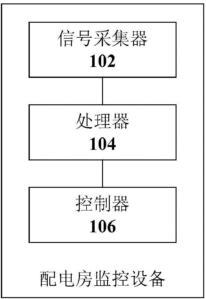
[0026] According to an embodiment of the present invention, a power distribution room monitoring device is provided, such as figure 1 As shown, the equipment includes:

[0027] 1) The signal collector 102 is provided with an analog signal interface and / or a digital signal interface for connecting the temperature sensor and / or the temperature sensor circuit, and the signal collector 102 is used to obtain and output the temperature sensor and / or the output of the temperature sensor circuit temperature parameters;

[0028] 2) The processor 104 is connected to the signal collector 102, and the processor 104 is used to output execution parameters according to the temperature parameter output by the signal collector 102;

[0029] 3) The controller 106 is connected to the processor 104. The controller 106 is used to connect to the temperature control device, and transmits a control signal corresponding to the execution parameter to the temperature control device according to the exe...

Embodiment 2

[0057] According to an embodiment of the present invention, a power distribution room monitoring system is also provided, such as Figure 5 As shown, the system can include:

[0058] 1) One or more temperature sensors 506 and / or temperature sensor circuits 506, and one or more temperature control devices 508 are arranged in the power distribution room;

[0059] 2) One or more power distribution room monitoring devices 502 according to any one of claims 1 to 9, each power distribution room monitoring device is connected to one or more temperature sensors 506 and / or one of the temperature sensor circuits 506 or more and one or more of the one or more temperature control devices 508;

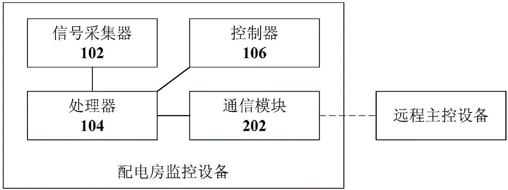
[0060] 3) The remote master control device 504 communicates data with each power distribution room monitoring device 502 through the communication module in each power distribution room monitoring device 502 .

[0061] Such as Figure 5As shown, in the embodiment of the present invention, a powe...


PUM


Abstract

The invention discloses monitoring equipment and monitoring system for an electrical distribution facility. The equipment comprises a signal acquisition device, a processor and a controller, wherein the signal acquisition device is provided with an analog signal interface and/or a digital signal interface and is used for being connected with a temperature sensor and/or a temperature sensor circuit; the signal acquisition device is used for acquiring and outputting a temperature parameter output by the temperature sensor and/or the temperature sensor circuit; the processor is connected with the signal acquisition device; the processor is used for outputting an execution parameter according to the temperature parameter output by the signal acquisition device; the controller is connected with the processor; the controller is used for being connected with temperature control equipment and transmitting a control signal corresponding to the execution parameter to the temperature control equipment according to the execution parameter output by the processor. The monitoring equipment and the monitoring system for the electrical distribution facility solve the technical problem that a manual patrolling mode is difficult to timely respond to variation of an operation temperature of the equipment in the electrical distribution facility.

Description

technical field [0001] The invention relates to the field of power supply safety, in particular to a monitoring device and system for a power distribution room. Background technique [0002] In the power supply system, the switching station usually refers to the distribution and transfer station between the load center area and two high-voltage substations. A collection of switching devices that supply power to electrical equipment, and in addition to power transmission, they can also play the role of outgoing line protection. In other words, switching stations can be regarded as the hub between the power supply system and electrical equipment. In order to be as close as possible to the load center area, the switching station is usually built near the intersection of the main road in the city, so how to ensure the power supply safety of the switching station has become a problem. [0003] The existing operation safety of the switch station, especially the monitoring of the ...

Claims


Application Information

Patent Timeline
Patent Type & Authority Applications(China)
IPC IPC(8): G05B19/418
CPCY02P90/02G05B19/042
Inventor 吴天齐张文超辛锋
Owner STATE GRID CORP OF CHINA
Why Eureka
Try Eureka