Micro-grid system capable of automatically realizing energy balance

An energy balancing and microgrid technology, applied in the field of microgrid systems, can solve the problems such as the inability to meet the fast automatic balance of system power and the high price of energy storage devices, and achieve the effects of taking into account the reliability of power supply, improving lifespan, and suppressing power fluctuations

Inactive Publication Date: 2015-06-03
CHENGDU DINGZHIHUI TECH
View PDF6 Cites 9 Cited by
  • Summary
  • Abstract
  • Description
  • Claims
  • Application Information

AI Technical Summary

Problems solved by technology

The traditional method is to use a single battery energy storage element to stabilize the system power, but due to the impact of frequent charging and discharging on the life of the battery pack and the single energy storage element often cannot meet the needs of rapid and automatic balance of system power
[0005] In addition, the price of large-scale energy storage devices is relatively expensive. Therefore, it is necessary to comprehensively consider the cost of transmission projects, the cost of energy storage devices, the revenue of power transmission, and the revenue of energy storage devices. Method for Optimal Configuration of Energy Storage Devices at Time-of-Capacity

Method used


Image

  • Micro-grid system capable of automatically realizing energy balance
  • Micro-grid system capable of automatically realizing energy balance
  • Micro-grid system capable of automatically realizing energy balance

Examples


Embodiment Construction

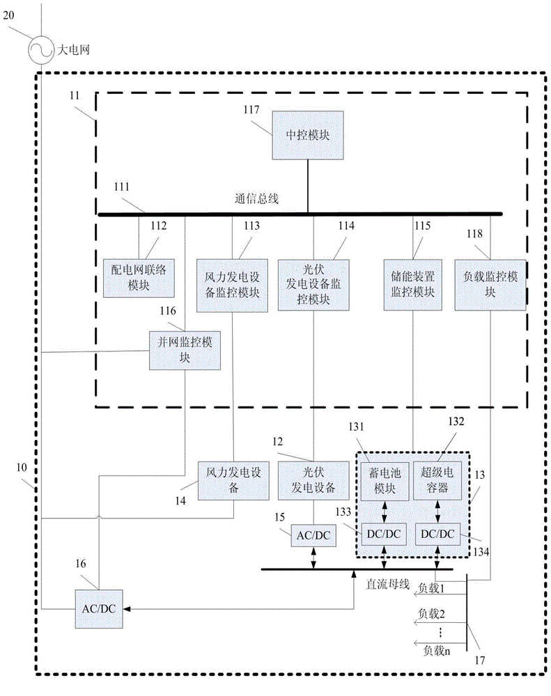
[0028] figure 1 It shows a microgrid 10 with an energy storage device that can stabilize power fluctuations according to the present invention. The microgrid 10 includes: photovoltaic power generation equipment 12, energy storage device 13, wind power generation equipment 14, and a AC / DC bidirectional converter module 1 16 connected to and isolated from large grid 20 , DC bus, AC / DC bidirectional converter module 2 15 for connecting photovoltaic power generation equipment 12 and DC bus, load 17 and monitoring device 11 .

[0029] see figure 1 , the energy storage device 13 includes a battery module 131, a supercapacitor 132 and bidirectional DC / DC converters 133 and 134 connected to the above-mentioned DC bus, wherein the bidirectional DC / DC converter 133 is connected to the battery module 131 and the DC bus, and the bidirectional DC / DC The inverter 134 is connected to the supercapacitor and the DC bus, and both the bidirectional DC / DC converters 133 and 134 may include a plu...


PUM


Abstract

The invention relates to a micro-grid system capable of automatically realizing energy balance. The micro-grid system comprises wind power generation equipment, photovoltaic power generation equipment, an energy storage device, a first AC/DC bidirectional commutation module, a DC bus, a second AC/DC bidirectional commutation module, loads in a micro-grid and a monitoring device, wherein the first AC/DC bidirectional commutation module is used for connecting the micro-grid with a large-scale power grid and isolating the micro-grid from the large-scale power grid; the second AC/DC bidirectional commutation module is used for connecting the wind power generation equipment, the photovoltaic power generation equipment and the DC bus; the energy storage device comprises a storage battery module, a super capacitor and a bidirectional DC/DC converter connected with the DC bus. According to the micro-grid system, generation power of the power generation equipment in the micro-grid and variation of the loads in the micro-grid can be forecast; power of a connection point of the micro-grid and the large-scale power grid can be tracked and forecast; an optimum control strategy can be made and implemented; the micro-grid is guaranteed to rapidly and stably provide active power and reactive power in the grid connection process according to the requirements of the large-scale power grid; the safety and the service life of the energy storage device can be promoted.

Description

Technical field [0001] The invention relates to a microgrid system capable of automatically realizing energy balance. Background technique [0002] Micro-grid (Micro-Grid), also translated as micro-grid, is a new type of network structure. It is a system unit composed of a group of micro-power sources, loads, energy storage devices and control devices. It can realize an autonomous system of self-control, protection and management. , it can run in parallel with the external power grid or run in isolation. [0003] As a supplement to the ultra-high voltage, long-distance, and large-grid power supply mode, the micro-grid based on wind power and photovoltaic power generation represents a new development direction of the power system. Wind energy and solar energy resources are clean and renewable energy, but there are problems of randomness and volatility, which bring a series of impacts to the power grid. The degree of power fluctuation directly affects the original power flow...

Claims


Application Information

Patent Timeline
Patent Type & Authority Applications(China)
IPC IPC(8): H02J3/32H02J3/38
CPCH02J3/32H02J3/383H02J3/386Y02E10/56Y02E10/76Y02E70/30
Inventor 许驰
Owner CHENGDU DINGZHIHUI TECH
Why Eureka
Try Eureka