Boost and buck driving circuit and lamp

A driving circuit, step-up and step-down technology, which is applied in the electronic field, can solve the problems such as the lighting LED is not bright, can not provide, burn out the lighting LED, etc., and achieve the effect of simple structure, convenient operation and high efficiency

Inactive Publication Date: 2015-06-03
SHENZHEN OCEANS KING LIGHTING ENG CO LTD +1
View PDF1 Cites 7 Cited by
  • Summary
  • Abstract
  • Description
  • Claims
  • Application Information

AI Technical Summary

Problems solved by technology

[0002] In recent years, with the rapid development of electronic technology, people always hope to change the voltage value connected to both ends of the load according to the specific load conditions. For example, when increasing the number of series-connected lighting LEDs in the load, the load module needs to be Boost, when reducing the number of LEDs in series in the load, it is necessary to step down the load module, but in the actual power supply, the power supply for power supply is 220V AC, and different voltages cannot be provided according to specific load conditions. Since the load is boosted or stepped down, when adding series lighting LEDs, since the partial voltage of each lighting LED cannot reach the driving voltage of the lighting LED, the lighting LED will be darker or not bright at all. When reducing When the lighting LEDs are connected in series, because the partial voltage of each lighting LED is too large, exceeding the limit voltage of the lighting LEDs and burning out the lighting LEDs, one power supply voltage specification can only provide the lighting voltage of a fixed number of lighting LEDs

Method used


Image

  • Boost and buck driving circuit and lamp
  • Boost and buck driving circuit and lamp

Examples


Embodiment Construction

[0019] The following will clearly and completely describe the technical solutions in the embodiments of the present invention with reference to the accompanying drawings in the embodiments of the present invention. Obviously, the described embodiments are only some, not all, embodiments of the present invention. Based on the embodiments of the present invention, all other embodiments obtained by persons of ordinary skill in the art without creative efforts fall within the protection scope of the present invention.

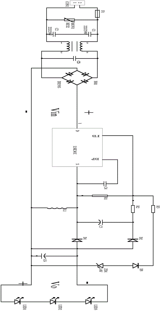
[0020] It should be noted that, in subsequent embodiments of the present invention, the first capacitor can be represented by capacitor C4, the second capacitor can be represented by capacitor C5, the third capacitor can be represented by capacitor C6, and the first diode can be represented by capacitor C6. The diode D2 is used to represent the second diode, the second diode can be represented by the diode D1, the third diode can be represented by the diode D3, the ...


PUM


Abstract

The embodiment of the invention discloses a boost and buck driving circuit, which comprises a power supply module, a control module, a feedback module, an energy storage module and a load module, wherein the power supply module is connected with the control module, the control module is respectively connected with the feedback module and the energy storage module, the energy storage module is respectively connected with the load module and the feedback module, when the control module detects boost triggering signals, the voltage of the energy storage module is controlled to be overlapped to the load module and realizes the boosting on the voltage of the load module, when the control module detects the voltage buck triggering signals of the feedback module, the energy storage module and the load module are subjected to voltage division, and the bucking is performed on the voltage of the load module. The circuit has the advantages that the boosting and bucking control on the voltage at the two ends of the load module can be simply, conveniently and fast realized according to the concrete load conditions.

Description

technical field [0001] The invention relates to the field of electronic technology, in particular to a boost-down drive circuit and a lamp. Background technique [0002] In recent years, with the rapid development of electronic technology, people always hope to change the voltage value connected to both ends of the load according to the specific load conditions. For example, when increasing the number of series-connected lighting LEDs in the load, the load module needs to be Boost, when reducing the number of LEDs in series in the load, it is necessary to step down the load module, but in the actual power supply, the power supply for power supply is 220V AC, and different voltages cannot be provided according to specific load conditions. Since the load is boosted or stepped down, when adding series lighting LEDs, since the partial voltage of each lighting LED cannot reach the driving voltage of the lighting LED, the lighting LED will be darker or not bright at all. When redu...

Claims


Application Information

Patent Timeline
Patent Type & Authority Applications(China)
IPC IPC(8): H05B37/02
CPCY02B20/40
Inventor 周明杰刘百顺
Owner SHENZHEN OCEANS KING LIGHTING ENG CO LTD
Why Eureka
Try Eureka