
Riveting positioning jig for hot melt machine

A technology for positioning fixtures and hot melt machines, which is applied in the manufacturing of multilayer circuits, electrical components, printed circuits, etc., can solve problems such as increased cost and energy consumption, waste of manpower, and potential safety hazards, and achieves simple structure, The effect of improving riveting capacity and improving labor efficiency

Active Publication Date: 2017-11-03
竞陆电子(昆山)有限公司
View PDF5 Cites 0 Cited by
  • Summary
  • Abstract
  • Description
  • Claims
  • Application Information

AI Technical Summary

Problems solved by technology

[0002] In the prior art, the original machine of the hot-melt machine comes with a combination carrier plate, which is fixed on the machine platform. The multi-layer boards that have been assembled on the plate are riveted. Since the machine is automatically riveted, during the riveting process, the personnel are in a waiting state, which causes a waste of man-hours
Moreover, the combination of multi-layer boards on the standby machine will also cause psychological instability factors such as fear, and there are also potential safety hazards.
Furthermore, at present, the hot-melt machine has its own stripping device, which is driven by an air cylinder and is used to separate the riveted board from the combined carrier. However, the stripping device that comes with this machine It is not easy to lift the board after riveting, and manual lifting is required, which is easy to cause damage to the board and waste of man-hours, and the stripping device is driven by a cylinder, which requires machine program control, which not only complicates the mechanism, but also increases the cost and energy consumption

Method used


Image

  • Riveting positioning jig for hot melt machine
  • Riveting positioning jig for hot melt machine

Examples


Embodiment

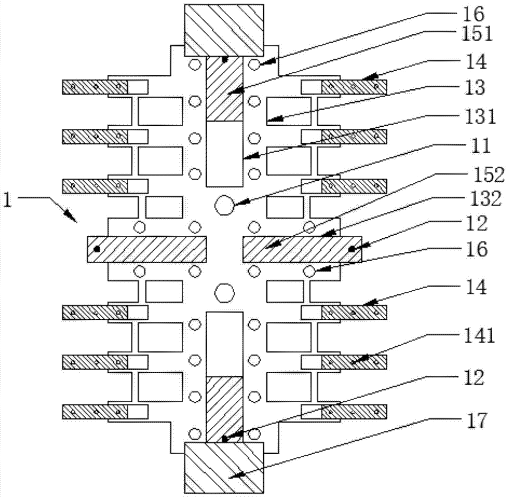
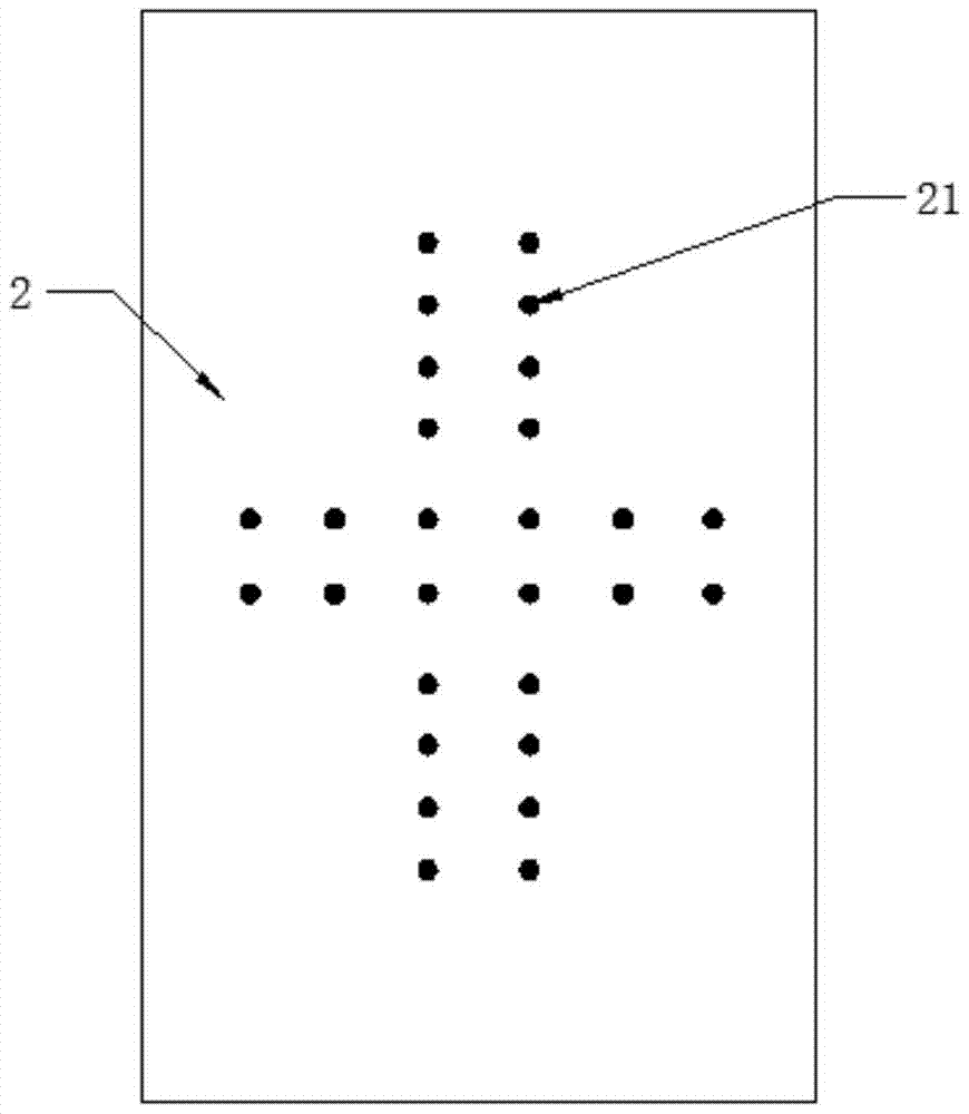
[0021] Embodiment: A riveting positioning jig for a hot-melt machine, which is composed of a combined carrier plate 1 and an ejector plate 2. There are two combined carrier plates, and the machine table of the hot-melt machine is provided with a There are two positioning pins for the combined tray, and the combined tray is provided with a positioning hole 11 corresponding to the positioning pin, and the combined tray is sleeved on the positioning pin of the machine through its positioning hole Realize the positioning connection with the machine platform. The combined tray is provided with positioning pins 12 corresponding to the alignment holes of the plate, and the plate passes through the alignment holes on the positioning pins of the combined tray to achieve positioning with the combined tray. connection, the combination tray is provided with a number of ejection holes 16, the upper surface of the ejection plate and the position corresponding to the ejection hole of the comb...


PUM


Abstract

The invention discloses a riveting positioning fixture for a hot-melt machine, which is composed of an ejector plate and two combined carrier plates, at least two positioning pins are arranged on the machine table, the combined carrier plate is provided with positioning holes, and the combined carrier plate The positioning pins of the machine table are inserted through the positioning holes to realize the positioning connection with the machine table. The combined carrier plate is provided with positioning pins corresponding to the alignment holes of the plate, and the plate is inserted through the alignment holes of the combined carrier plate. The positioning pin realizes the positioning connection with the combination carrier plate. The combination carrier plate is provided with a number of ejection holes. The upper surface of the ejection plate and the part corresponding to the ejection holes of the combination carrier plate have ejection pins. When the upper surface of the ejection board is ejected, the upper end of the ejection pin of the ejection board passes through the ejection hole of the combined carrier board. The invention enables operators to use another combination carrier plate for combination within the riveting time of the machine, which can increase the labor efficiency by 1 / 3, and can increase the riveting production capacity by 50%, and is convenient for riveting boards from combination detached from the tray.

Description

technical field [0001] The invention belongs to the field of printed circuit board manufacturing, and in particular relates to an improved structure of a combined carrier plate of a hot-melt machine. Background technique [0002] In the prior art, the original machine of the hot-melt machine comes with a combination carrier plate, which is fixed on the machine platform. The assembled multi-layer boards on the plate are riveted. Since the machine is automatically riveted, during the riveting process, the personnel are in a waiting state, which causes a waste of man-hours. Moreover, the combination of multi-layer boards on the standby machine will also cause psychological instability factors such as fear, and there are also potential safety hazards. Furthermore, at present, the hot-melt machine has its own stripping device, which is driven by an air cylinder and is used to separate the riveted board from the combined carrier. However, the stripping device that comes with this...

Claims


Application Information

Patent Timeline
Patent Type & Authority Patents(China)
IPC IPC(8): H05K3/00H05K3/46
Inventor 李泽清
Owner 竞陆电子(昆山)有限公司
Learn More