Disengagement system for a clutch of a motor vehicle

A separation system and clutch technology, applied in non-mechanical drive clutches, fluid drive clutches, clutches, etc., to achieve the effect of reducing tolerance chains, reducing costs, and requiring less precision

Inactive Publication Date: 2015-06-03
SCHAEFFLER TECH AG & CO KG
View PDF7 Cites 8 Cited by
  • Summary
  • Abstract
  • Description
  • Claims
  • Application Information

AI Technical Summary

Problems solved by technology

[0007] A further disadvantage is that the magnet must be guided precisely / repeatably and without play to the Hall sensor and the sensor integrated on the sensor circuit board must be positioned extremely precisely and must be placed on the main board at an angle of 90°

Method used


Image

  • Disengagement system for a clutch of a motor vehicle
  • Disengagement system for a clutch of a motor vehicle
  • Disengagement system for a clutch of a motor vehicle

Examples


Embodiment Construction

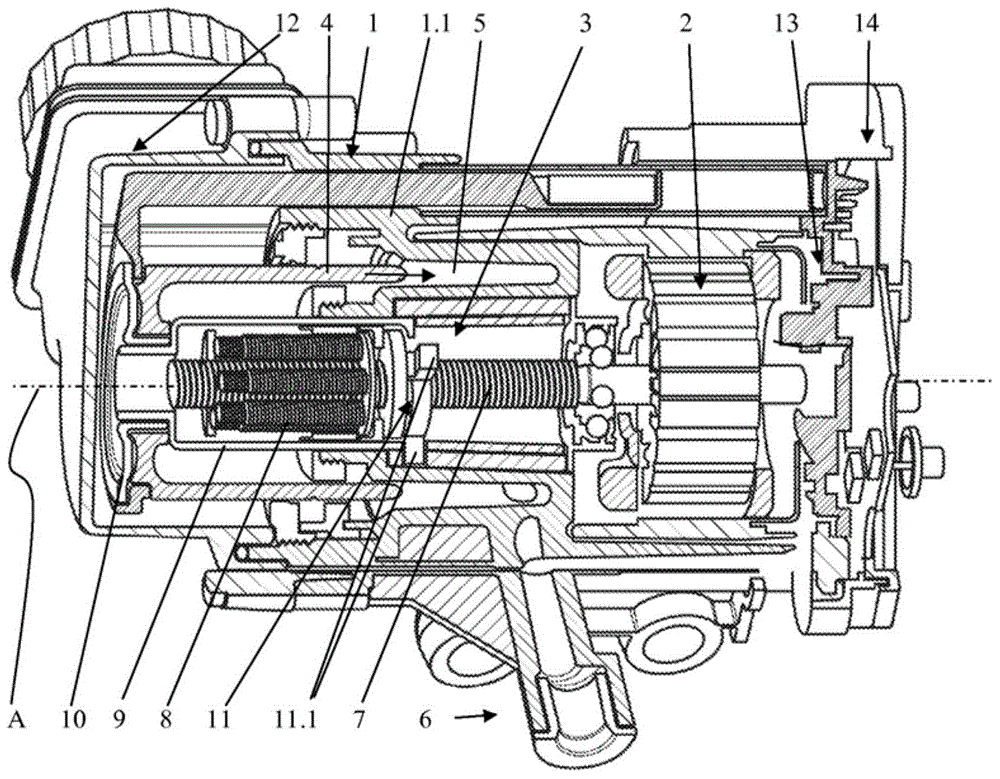
[0039] exist figure 1 A longitudinal sectional view of the separation system according to the invention is shown in to illustrate the principle structure. The disconnect system is designed here as a disconnect in the form of a hydraulic clutch actuator (HCA), wherein the master cylinder 1 can be actuated via the transmission 3 by means of a drive in the form of an electric motor 2 .

[0040] In the housing 1 . 1 of the master cylinder 1 , a piston 4 (annular piston) is arranged axially displaceable via a transmission 3 when the electric motor 2 is actuated. When the piston 4 is actuated in the axial direction, here to the right in the direction of the arrow, pressure builds up in the pressure chamber 5 formed by the housing 1 and the piston 4 . The pressure chamber 5 is connected via a pressure medium connection 6 and a not shown hydraulic line to a slave cylinder, also not shown, which actuates a clutch (not shown) via a release mechanism.

[0041] The transmission 3 is in ...


PUM


Abstract

The invention relates to a disengagement system for a clutch of a motor vehicle, using a drive which is in operative connection via a gear with a piston mounted such that the piston can be displaced axially in a housing, and wherein the piston, when actuated, builds up pressure in a pressure chamber formed by the housing and piston, said disengagement system comprising a sensor system for detecting the position of the piston. The disengagement system is characterised in that an inductive sensor system is integrated in the disengagement system, the sensor system comprising an inductive sensor fixed to the housing by means of which the position of an electrically conductive object (target) to be detected can be registered, wherein the target is integrated in the piston or in a component of the disengagement system axially displaceable complementary to the piston, or is designed in the form of at least one region of a component displaceable complementary to the piston.

Description

technical field [0001] The invention relates to a release system for a clutch of a motor vehicle, in particular of the type of a hydraulic clutch actuator (HCA) with means for position determination and / or displacement measurement of a piston. Background technique [0002] To determine the position or the displacement in the clutch disengagement system, various technical solutions are used which use the interaction of an information transmitter / reference transmitter (sensor element) designed as a magnet with a sensor / sensor arrangement. Typically, the magnet is associated with the piston, which is the movable part of the fluid cylinder, while the sensor is fixed on the cylinder housing which is fixed relative to the piston. [0003] A clutch actuator is known from document DE 103 16 422 A1, which consists of a drive motor, such as an electric motor, wherein the electric motor is connected via a transmission, such as a worm drive, a spur gear, a crankshaft Or the screw drive...

Claims


Application Information

Patent Timeline
Patent Type & Authority Applications(China)
IPC IPC(8): F16D25/08
CPCF16D25/08F16D2025/081F16D2300/18
Inventor 马库斯·迪特里希
Owner SCHAEFFLER TECH AG & CO KG
Why Eureka
Try Eureka