Mechanical Filter Panel Piping Connection Structure

A technology of mechanical filter and connection structure, applied in the field of filters, can solve the problems such as the inability to drain the liquid in the filter tank, the inability to know the leakage of the key valve, the uneven distribution of the liquid, etc., so as to ensure the water quality, the overall structure is simple, and the structural design reasonable effect

Inactive Publication Date: 2017-01-11
4R WATER TREATMENT SYST
View PDF5 Cites 0 Cited by
  • Summary
  • Abstract
  • Description
  • Claims
  • Application Information

AI Technical Summary

Problems solved by technology

[0004] 1. During normal filtration, if valve 2 and valve 3 are leaking, there will be unfiltered water in the water outlet, which will affect the water quality
[0005] 2. If the traditional valve does not have a leak detection device, it is impossible to know whether the key valve is leaking
[0006] 3. The area where the two large partitions meet the inner wall of the tank body 7 is large, forming many sanitary corners and affecting the quality of water
[0007] 4. There is no water distributor, and the liquid distribution is uneven, which affects the filtering effect
[0008] 5. The liquid in the filter tank cannot be drained

Method used


Image

  • Mechanical Filter Panel Piping Connection Structure
  • Mechanical Filter Panel Piping Connection Structure
  • Mechanical Filter Panel Piping Connection Structure

Examples


Embodiment Construction

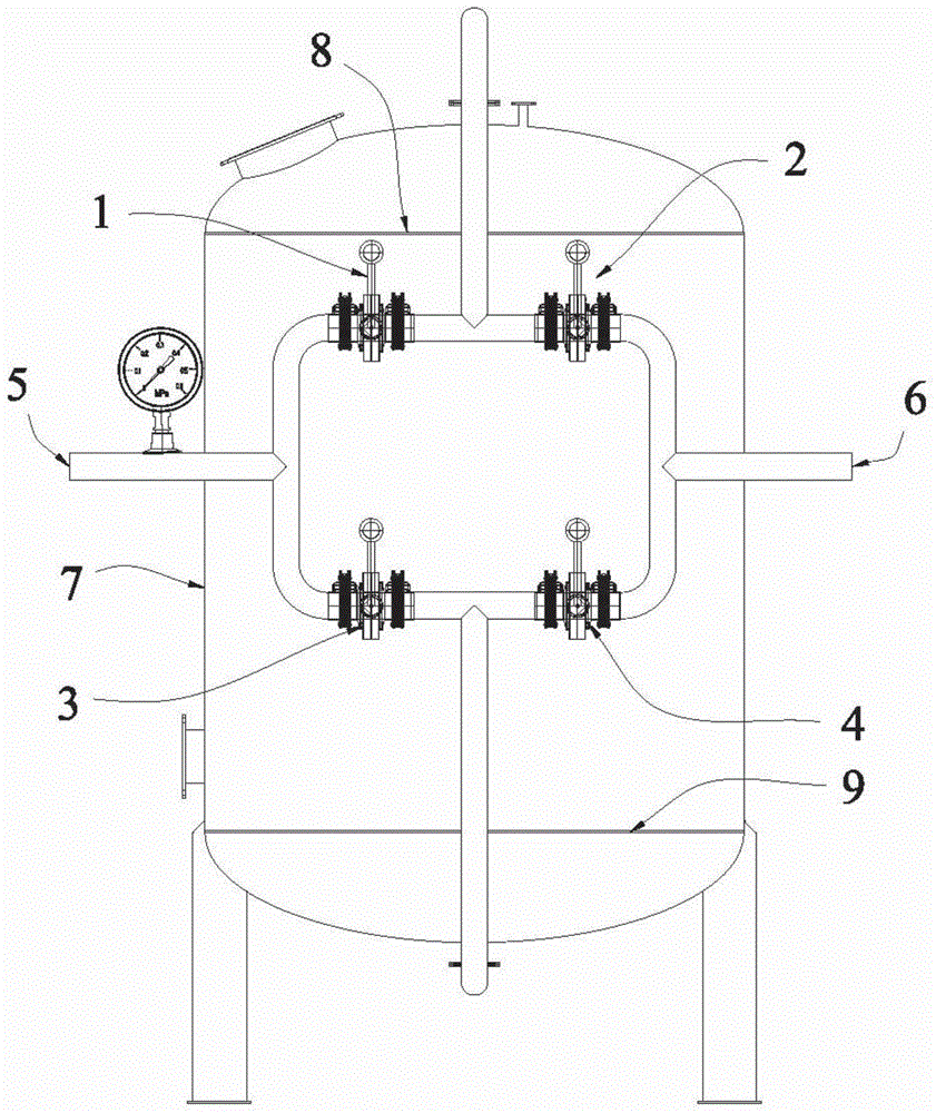
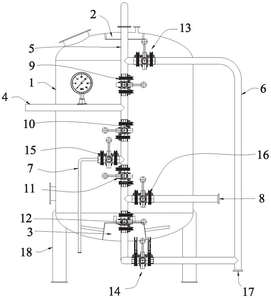
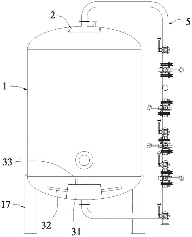
[0023] see figure 2 and image 3 , a mechanical filter panel pipe connection structure provided in this embodiment, which includes a tank body 1, a water distributor 2, a water collector 3, a water inlet pipe body 4, a main pipe body 5, a backwash pipe body 6, and a leak detection pipe Body 7, filter outlet pipe body 8 and valve body A9, valve body B10, valve body C11, valve body D12, valve body E13, valve body F14, valve body G15, valve body H16.

[0024] Specifically, the water distributor 2 is located at the top position in the tank body 1, the water collector 3 is located at the bottom position in the tank body 1, and the main body 5 is located at a side position of the tank body 1, preferably Yes, the main body 5 is parallel to the central axis of the tank body 1 . The upper end of the main body 5 extends into the tank body 1 to be connected with the water distributor 2, and the lower end extends into the tank body 1 to be connected to the water collector 3. The valve ...


PUM


Abstract

The invention discloses a novel mechanical filter panel pipeline connection mode which comprises a tank body, a water distributor, a water collector, a water feeding pipe body, a main pipe body, a backwashing pipe body, a leakage detection pipe body, a filtering water discharging pipe body and valve bodies from A to H, wherein the water distributor is arranged at the top in the tank body; the water collector is positioned at the bottom position in the tank body; the valve bodies from A to D are arranged on the main pipe body at intervals in sequence from top to bottom. The novel mechanical filter panel pipeline connection mode is reasonable in structural design, and the problem of water leakage of a key valve is effectively solved; furthermore, the probability of water leakage of the key valve is greatly reduced; even if the valve body B and the valve body C leak water simultaneously, the phenomenon that filtered water is mixed with non-filtered water can not occur, so that the water quality is guaranteed; the contact area between the water distributor and the water collector as well as the tank body is relatively small, and the sanitary dead corners are greatly reduced; meanwhile, the water distributor is ingeniously arranged at the top of the tank body, so that water can be uniformly distributed on filtering substances, and the filtering effect is enhanced; furthermore, the operation is simple, and the wide popularization and application are facilitated.

Description

technical field [0001] The invention relates to the technical field of filters, in particular to a mechanical filter panel pipeline connection structure. Background technique [0002] see figure 1 , is the schematic diagram of the traditional filter; the workflow path is as follows: 1. During normal filtration: water → valve 1 → tank body 7 → upper partition 8 → filter material → lower partition 9 → valve 4 → water outlet 6. In this process, only valve 4 and valve 1 are open. 2. When backwashing, water → valve 3 → tank body 7 → lower partition 9 → filter material → upper partition 8 → valve 2 → water outlet 6. Only valve 2 and valve 3 are open during this process. [0003] The disadvantages of traditional filters are as follows: [0004] 1. During normal filtration, if valve 2 and valve 3 are leaking, there will be unfiltered water mixed in the water outlet, which will affect the water quality. [0005] 2. If the traditional valve does not have a leak detection device, ...

Claims


Application Information

Patent Timeline
Patent Type & Authority Patents(China)
IPC IPC(8): B01D35/00B01D35/16
CPCB01D35/00B01D35/16
Inventor 谢民勇吴建航
Owner 4R WATER TREATMENT SYST
Why Eureka
Try Eureka