Ultrasonic welding device and ultrasonic welding method for controlling continuous ultrasonic welding processes

An ultrasonic and processing device technology, applied in the field of continuous ultrasonic welding process, can solve the problems of no longer bonding force of seams, unsatisfactory welding effect, and difficulty in achieving uniform quality of welding.

Active Publication Date: 2015-06-10
BRANSON ULTRASCHALL NIEDERLASSUNG DER EMERSON TECH
View PDF9 Cites 16 Cited by
  • Summary
  • Abstract
  • Description
  • Claims
  • Application Information

AI Technical Summary

Problems solved by technology

In fact, these profiles are notoriously difficult to achieve a uniform quality weld
Since the stress of the fabric material is greater than the blocking force, the support structure and the gap of the drive assembly of the ultrasonic oscillation unit will cause the sonotrode to yield or retreat, and the above gap will be excessively opened, so that the subsequently formed seam will no longer have proper binding force
Therefore, the welding effect will be unsatisfactory, especially in the position of the seam

Method used


Image

  • Ultrasonic welding device and ultrasonic welding method for controlling continuous ultrasonic welding processes
  • Ultrasonic welding device and ultrasonic welding method for controlling continuous ultrasonic welding processes
  • Ultrasonic welding device and ultrasonic welding method for controlling continuous ultrasonic welding processes

Examples


Embodiment Construction

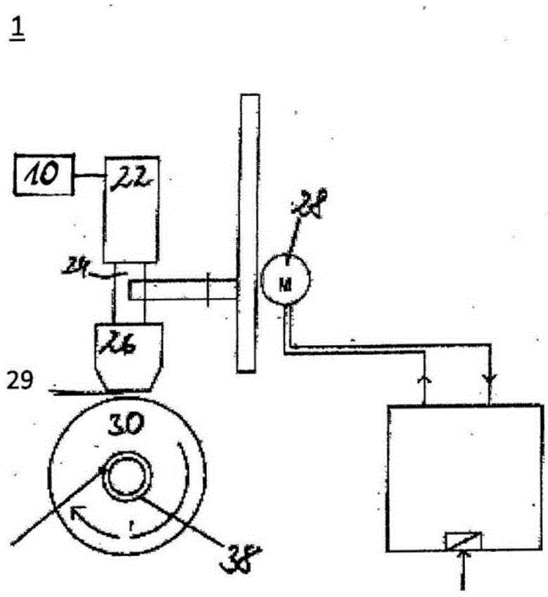
[0041] figure 1 The basic structure of an ultrasonic processing device 1 is shown. The ultrasonic processing device 1 comprises a sonotrode 10, a converter 22, a booster 24, a linearly movable sonotrode 26, and a roller or an anvil 30 used as a reverse tool respectively, the sonotrode 26 and the roller Between 30 gaps 29 are formed.

[0042] By simulating the structure of the above-mentioned ultrasonic processing device 1, it can be known that a better option is to provide a rotatable sonotrode (not shown in the figure). In this case, at least one sonotrode is arranged on the roller. The sonotrode roller is carried or supported rotatably about a central axis. The outer region of the sonotrode roller has the function of the outer surface of the roller 30, which will be described in detail below. In order to adjust the gap between the rotating sonotrode roller and the anvil arranged opposite it, the sonotrode roller and / or the anvil (not shown) can be moved linearly. The mo...


PUM


Abstract

An ultrasonic processing method and an ultrasonic processing device may include a controlling/regulating module, preferably a digital controlling/regulating module, which is integrated into a signal processing of the ultrasonic generator so that a plurality of generator data with respect to the ultrasonic generator are processible in the ultrasonic generator. At this, a power actual value Pist is compared with a power reference value Psoll of the ultrasonic generator via a gap regulator in the controlling/regulating module to specify a position reference value POSsoll of the sonotrode relative to the roll for adjustment of the power reference value Psoll of the ultrasonic generator, and/or a power actual value Pist is compared with a power reference value Psoll of the ultrasonic generator via an amplitude regulator in the controlling/regulating module to specify an amplitude reference value Asoll to the ultrasonic generator for adjustment of the power reference value Psoll.

Description

technical field [0001] The invention relates to an ultrasonic welding device and an ultrasonic welding method for controlling or regulating a continuous ultrasonic welding process for ultrasonic welding of textile materials. Background technique [0002] Devices for continuous ultrasonic welding of textile materials are widely known. In these devices, the ultrasonic oscillating unit usually comprises a transducer, generally an electro-acoustic transducer, on which the sonotrode is mounted via an amplitude conversion component also called a booster. However, there are also embodiments in which the sonotrode is directly connected to the transducer. In such an ultrasonic oscillating unit, either the oscillating unit is supported in the converter case, or the amplitude conversion member is supported by a retaining ring, or the sonotrode is supported by a base. These support structures are usually arranged on, or at least close to, the oscillation nodes of the ultrasonic oscill...

Claims


Application Information

Patent Timeline
Patent Type & Authority Applications(China)
IPC IPC(8): B23K20/10B06B3/02B29C65/08
CPCB06B3/02B23K20/10B29C65/08B29C66/9321B23K20/103B29C65/085B29C65/086B29C66/1122B29C66/232B29C66/43B29C66/45B29C66/83411B29C66/83511B29C66/9231B29C66/9241B29C66/92611B29C66/92613B29C66/92921B29C66/9592B29C66/932B06B1/0246B29C66/961B29C66/8242B29C66/9516B29L2009/00B29C66/942
Inventor 克里斯蒂安·希格
Owner BRANSON ULTRASCHALL NIEDERLASSUNG DER EMERSON TECH
Why Eureka
Try Eureka