Point-type plastic filling device of injection mold

An injection mold, point-type technology, which is applied in the design and manufacture of the injection mold inlet, and the injection mold point-type injection system field, can solve the problem that the sprue sleeve and the ejector plate are prone to flash and sprue sleeves. The extrusion strength with the ejector plate is high, and the difficulty and cost of mold maintenance are increased, so as to improve the heat loss too fast, save the raw materials of plastic particles, and improve the service life.

Inactive Publication Date: 2015-06-10
北京世东凌云科技有限公司
View PDF2 Cites 2 Cited by
  • Summary
  • Abstract
  • Description
  • Claims
  • Application Information

AI Technical Summary

Problems solved by technology

Although this kind of plastic inlet design structure is easy to process, when the injection molding machine mass-produces molds, flashes are likely to appear at the seal between the sprue sleeve and the pusher plate
In addition, due to the high mutual extrusion strength between the sprue sleeve and the pusher plate, it is easy to bite and break the sprue sleeve
Once the sprue sleeve is broken or damaged, the mold must be removed for repair or replacement each time, which not only increases the difficulty and cost of mold maintenance, delays the product delivery cycle, but also causes waste of plastic pellets due to mold loading and unloading

Method used


Image

  • Point-type plastic filling device of injection mold
  • Point-type plastic filling device of injection mold
  • Point-type plastic filling device of injection mold

Examples


Embodiment Construction

[0019] In order to further illustrate the technical means and beneficial effects adopted by the present invention to achieve its purpose, and to enable those skilled in the art to implement the present invention according to the detailed introduction of this specification, the following is combined with the accompanying drawings and preferred embodiments of the present invention , the specific embodiments of the present invention will be described in detail below.

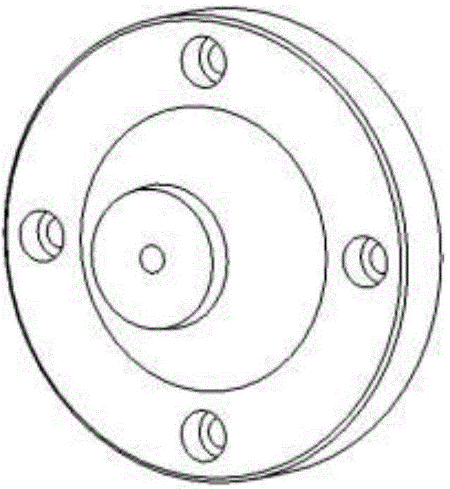
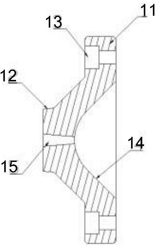
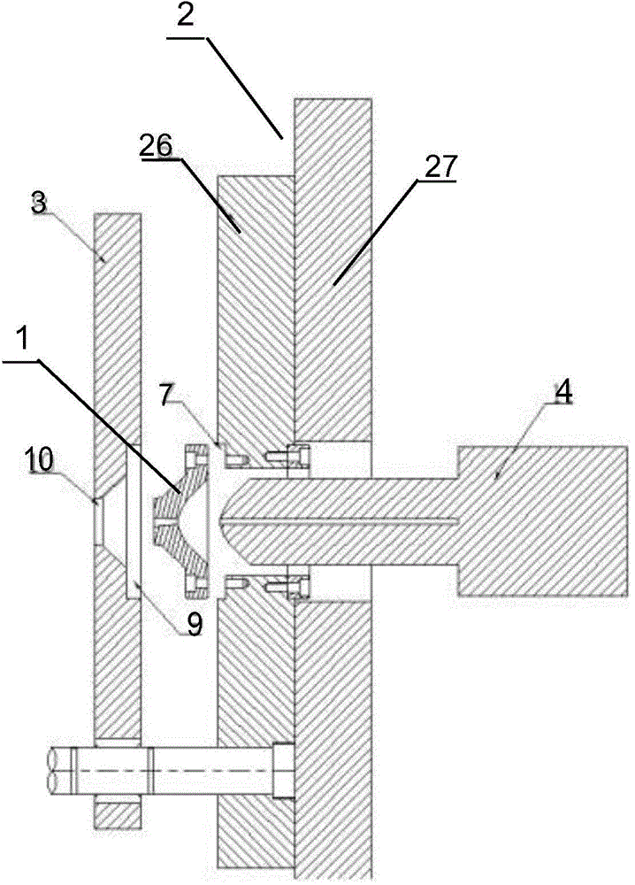
[0020] figure 1 and figure 2 Respectively, a schematic structural view and a cross-sectional view of a sprue sleeve of a point-type glue feeding device for an injection mold according to the present invention, image 3 It is a cross-sectional view of a point-type glue feeding device for an injection mold according to the present invention. see Figure 1 to Figure 3 , A point-type glue feeding device for an injection mold of the present invention includes: a sprue sleeve 1, a mechanical plate part 2, a pusher pl...


PUM


Abstract

The invention provides a point-type plastic filling device of an injection mold. The point-type plastic filling device comprises a sprue bush, a mechanical plate part, a pushing plate and a lengthened injection head. The sprue bush is machined by virtue of a turning lathe. The sprue bush comprises a sprue bush fixing seat which is arranged at the bottom, a conical sealing compound which is arranged at the front end, a fixed screw, and an arc contact surface and a plastic feeding opening which are formed at the bottom of the sprue bush fixing seat. The point-type plastic filling device is integrally designed and machined, and the sprue bush is arranged between a mold mechanical plate and the pushing plate, so that the service life of the mold can be prolonged, and the machining efficiency of the injection molding procedure can be effectively improved.

Description

technical field [0001] The invention belongs to the technical field of injection molds, and relates to the design and manufacture of plastic inlets of injection molds. In particular, it relates to a point-type glue-feeding system for an injection mold composed of an improved sprue sleeve and a pusher plate. Background technique [0002] At present, in the field of injection mold design and manufacturing technology, point-type glue inlet is a common injection method, and the inlet is usually directly inserted into the mechanical plate and pusher plate of the upper mold by a standard sprue sleeve. , and then fix the T-shaped head at one end of the sprue sleeve to the mechanical plate with screws, and insert the other end into the pusher plate and rub against it. Although this kind of plastic inlet design structure is easy to process, when the injection molding machine mass-produces molds, flashes are prone to appear at the seal between the sprue sleeve and the ejector plate. ...

Claims


Application Information

Patent Timeline
Patent Type & Authority Applications(China)
IPC IPC(8): B29C45/27
CPCB29C45/2701B29C2045/2719
Inventor 李斌王国有
Owner 北京世东凌云科技有限公司
Why Eureka
Try Eureka