Supersonic nozzle for miniature ink jet printing

A supersonic nozzle and micro-injection technology, which is applied in the direction of additive processing, etc., can solve the problems of poor jet convergence at the nozzle outlet, short distance in the supersonic section, and large flow, so as to prevent clogging, reduce air flow, and reduce The effect of energy loss

Inactive Publication Date: 2015-06-10
CHINA THREE GORGES UNIV
View PDF9 Cites 3 Cited by
  • Summary
  • Abstract
  • Description
  • Claims
  • Application Information

AI Technical Summary

Problems solved by technology

[0006] The purpose of the present invention is to aim at the existing supersonic nozzles used for micro-jet printing in the process of preparing high-quality film layer units, the flow rate is relatively large, the distance of the supersonic section is short, and the nozzle outlet jet convergence is not good, which is easy to cause Provide a supersonic nozzle for micro jet printing

Method used


Image

  • Supersonic nozzle for miniature ink jet printing
  • Supersonic nozzle for miniature ink jet printing
  • Supersonic nozzle for miniature ink jet printing

Examples


Embodiment 1

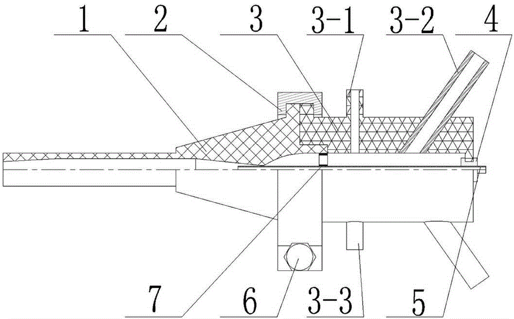
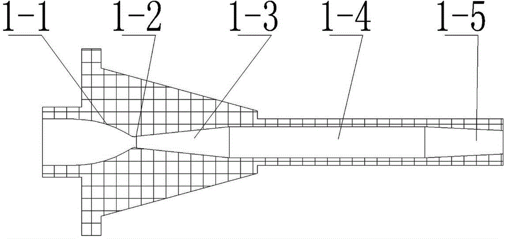
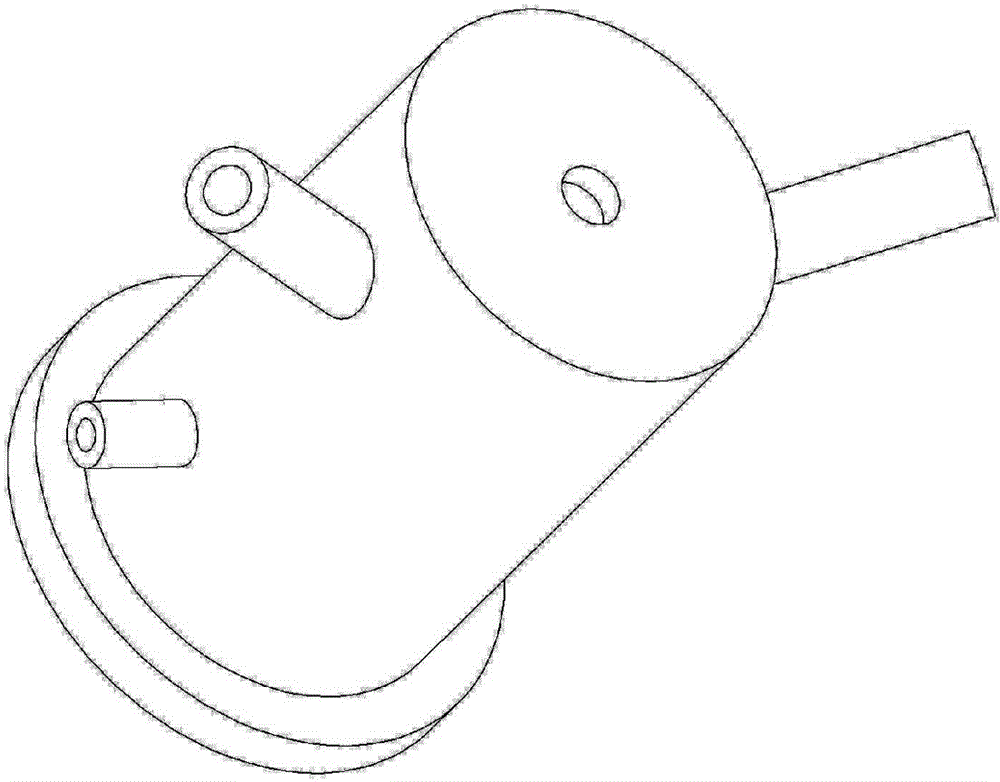
[0031] Such as Figure 1-6 As shown, it is a schematic structural diagram of a supersonic nozzle for micro-jet printing, which mainly includes a Laval nozzle 1, a locking block 2, an air chamber body 3, a pressure probe interface 3-1, and an air source inlet 3 -2. Temperature probe interface 3-3, U-shaped plug 4, powder feeding pipe 5, fastening bolt 6, ring grid 7, Laval nozzle 1 and gas chamber body 3 are connected by locking block 2 to form an axisymmetric whole , and fixed by fastening bolts 6, the front end of the gas chamber body 3 is symmetrically distributed with pressure probe interfaces 3-1 and temperature probe interfaces 3-3, and the end of the gas chamber body 3 is symmetrically inserted obliquely with multiple gas source inlets 3 -2, the tail is equipped with a coaxial powder feeding pipe 5 through a U-shaped plug 4, and an annular grid 7 is arranged at the contact point between the Laval nozzle 1 and the gas chamber body 3, and the high-pressure gas and powd...

Embodiment 2

[0038] A supersonic nozzle for microjet printing, which mainly includes a Laval nozzle 1, a locking block 2, an air chamber body 3, a pressure probe interface 3-1, an air source inlet 3-2, and a temperature probe interface 3 -3, U-shaped plug 4, powder feeding pipe 5, fastening bolt 6, ring grid 7, the Laval nozzle 1 and the gas chamber body 3 are connected into an axisymmetric whole through the locking block 2, and the fastening bolt 6 is used Fixed, pressure probe interface 3-1 and temperature probe interface 3-3 are symmetrically distributed up and down the front end of the gas chamber body 3, multiple gas source inlets 3-2 are inserted symmetrically and obliquely at the end of the gas chamber body 3, and the tail passes through a U-shaped The plug 4 is equipped with a coaxial powder feeding pipe 5, and an annular grid 7 is arranged at the contact point between the Laval nozzle 1 and the gas chamber body 3, and the high-pressure gas and powder are gathered and sprayed ou...

Embodiment 3

[0043] A supersonic nozzle for microjet printing, which mainly includes a Laval nozzle 1, a locking block 2, an air chamber body 3, a pressure probe interface 3-1, an air source inlet 3-2, and a temperature probe interface 3 -3, U-shaped plug 4, powder feeding pipe 5, fastening bolt 6, ring grid 7, the Laval nozzle 1 and the gas chamber body 3 are connected into an axisymmetric whole through the locking block 2, and the fastening bolt 6 is used Fixed, pressure probe interface 3-1 and temperature probe interface 3-3 are symmetrically distributed up and down the front end of the gas chamber body 3, multiple gas source inlets 3-2 are inserted symmetrically and obliquely at the end of the gas chamber body 3, and the tail passes through a U-shaped The plug 4 is equipped with a coaxial powder feeding pipe 5, and an annular grid 7 is arranged at the contact point between the Laval nozzle 1 and the gas chamber body 3, and the high-pressure gas and powder are gathered and sprayed ou...


PUM

PropertyMeasurementUnit
lengthaaaaaaaaaa
lengthaaaaaaaaaa
lengthaaaaaaaaaa

Abstract

The invention discloses a supersonic nozzle for miniature ink jet printing, wherein a De Laval nozzle is connected with a gas chamber body by virtue of a locking block so as to be formed into an axisymmetric whole and fixed by virtue of a fastening bolt, and the front end of the gas chamber body is symmetrically provided with a pressure probe interface and a temperature probe interface; symmetric air source inlets are tipsily inserted in the rear end of the gas chamber body, the tail part of the gas chamber body is provided with a coaxial powder feeding pipe by virtue of a U-shaped plug, the connecting part of the De Laval nozzle and the gas chamber body is provided with an annular grid mesh, and high-pressure gas and a power body are converged in the De Laval nozzle and sprayed out. The supersonic nozzle adopts coaxial powder feeding, and the powder feeding pipe is directly communicated with the laryngeal of the De Laval nozzle, so that blockage is prevented; the airflow is uniform and stable due to the effects of the multiple symmetrically-distributed air source inlets and the annular grid mesh, so that acceleration of the powder body is facilitated; a flow pass in the De Laval nozzle is in a regular streamline shape, flow is small, the supersonic speed segment distance is long, the converging of a jet flow outlet is relatively good, and the supersonic nozzle has relatively good application prospect.

Description

technical field [0001] The invention relates to a nozzle, in particular to a micro-jet printing supersonic nozzle based on the principle of cold spraying. Background technique [0002] In recent years, the new concept of micro-manufacturing (Micro-manufacture) has been introduced into material design and research, and is becoming a hot spot in academia and industry. Development has brought new challenges to manufacturing technology, and only the use of new moldless molding, especially jet printing technology, is expected to succeed. [0003] Jet printing technology is an additive manufacturing solution that uses aerodynamic principles to focus on the deposition of precise nano / micro-scale materials. Usually, the material to be formed is printed directly onto the carrier through the printer after corresponding pre-treatment For molding, the shape and size of the molded body are controlled by the computer. It can be used for bulk material molding, and is more suitable for thi...

Claims


Application Information

Patent Timeline
Patent Type & Authority Applications(China)
IPC IPC(8): B29C67/00B33Y30/00
Inventor 吴海华郭辉熊盼魏正英
Owner CHINA THREE GORGES UNIV
Why Eureka
Try Eureka