Cement bagging machine experiment table

It is a technology of test bench and packaging, which is applied in the direction of packaging, transportation and packaging, and the type of packaged items. It can solve the problems of not easy to realize control, high operating cost, and high labor intensity, so as to save manpower and material resources and discharge materials. Precise, easy maintenance effect

Inactive Publication Date: 2015-06-10
XINXIANG VOCATIONAL & TECHN COLLEGE
View PDF7 Cites 3 Cited by
  • Summary
  • Abstract
  • Description
  • Claims
  • Application Information

AI Technical Summary

Problems solved by technology

This kind of cement packing machine has the defects of high labor intensity, high operating cost and difficult control

Method used


Image

  • Cement bagging machine experiment table

Examples


Embodiment Construction

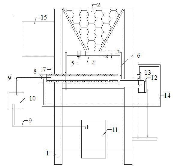
[0008] Embodiments are described in detail with reference to the accompanying drawings. A cement packing machine test bench, a storage funnel 2 is fixed on the top of the frame 1, a distribution bin 3 is fixed on the frame 1 below the storage funnel 2, and a storage funnel is arranged above the distribution bin 3 2. The feed port opposite to the feed port. The feed port is provided with a butt-closed bin door 4, and the bin door 4 is driven by a drive motor 5 arranged on the distribution bin 3. One side of the distribution bin 3 The plate 6 is provided with threaded holes, and the threaded holes are screwed with an air pipe 7, and the air pipe 7 on the outside of the material distribution bin 3 is connected to the air inlet pipe 9 through the air circuit control valve 8, and the air inlet pipe 9 is provided with an air storage tank 10. The end of the trachea 9 is connected to the air pump 11 arranged at the bottom of the frame 1, the end of the trachea 7 inside the distributio...


PUM


Abstract

The invention discloses a cement bagging machine experiment table. A storage hopper is fixedly arranged at the top of a rack, and a material dividing bin is fixedly arranged on the rack under the storage hopper. A feeding opening opposite to a blanking opening of the storage hopper is formed above the material dividing bin. A threaded hole is formed in one side plate of the material dividing bin, and an air pipe is screwed in the threaded hole. A discharging opening is formed in the other side plate of the material dividing bin and connected with a discharging pipeline, and a pneumatic valve is arranged on the discharging pipeline. An electric cabinet is arranged on one side of the rack, and a controller is arranged in the electric cabinet. According to the invention, gas equipment is adopted to replace a mechanical device for discharging, so that filling equipment can accurately discharge materials and can complete one-time discharging within the fixed time. The cement filling and weight control are completed within the set time period according to equipment requirements, maintenance is convenient, and manpower and material resources are saved.

Description

technical field [0001] The invention belongs to the technical field of cement packaging equipment, and in particular relates to a cement packaging machine test bench. Background technique [0002] At present, the cement packing machines used by many cement factories in the market adopt a mechanical structure, and the motor drives the screw mechanism to push the dry cement powder forward to meet the requirement of subpackaging the dry cement powder. This cement packing machine has the defects of high labor intensity, high operation cost and difficult easy control. Contents of the invention [0003] The technical problem solved by the invention is to provide a cement packing machine test bench with simple structure and convenient control. [0004] In order to solve the above technical problems, the present invention adopts the following technical scheme, a cement packaging machine test bench, which is characterized in that: a storage funnel is fixed on the top of the frame,...

Claims


Application Information

Patent Timeline
Patent Type & Authority Applications(China)
IPC IPC(8): B65B1/16B65B1/40
CPCB65B1/16B65B1/40
Inventor 苗晋涛裴建军朱运晓曹观峰
Owner XINXIANG VOCATIONAL & TECHN COLLEGE
Why Eureka
Try Eureka