Double column-type transition hydraulic support

A hydraulic support and column type technology, which is applied in mine roof supports, mining equipment, earthwork drilling and mining, etc., can solve problems such as difficulty in automation, unbalanced force on front and rear columns, damage to columns and components, etc., and achieve electro-hydraulic control and automation, easy electro-hydraulic control and automation, simple overall structure

Inactive Publication Date: 2015-06-10
HUATING COAL GRP
View PDF9 Cites 0 Cited by
  • Summary
  • Abstract
  • Description
  • Claims
  • Application Information

AI Technical Summary

Problems solved by technology

[0002] When the two-column hydraulic support in the prior art is used as a transition hydraulic support, due to the small rear space in the structure, it cannot accommodate the installation of the front and rear scraper machine heads and tail drive parts, so the two-column hydraulic support can only It is used as an intermediate support (also called a basic support), but not as a transitional support
In addition, the force on the front and rear columns of the four-column transitional hydraulic support is unbalanced. Often, the force on the two rear columns is large, so that the second half of the bracket is crushed to death, resulting in a height lower than the required height at the rear of the bracket, while the front two columns are stressed. The force is small and the front part of the bracket is much higher than the rear half of the bracket, which causes problems such as unbalanced force on the front and rear columns and low utilization rate of working resistance, especially when the coal is discharged, it is easy to form the tension state of the rear column, which leads to the failure of the column and components. The damage is serious, resulting in poor overall stability of the bracket, and the overall structure and control of this type of rack are complex, making it difficult to automate

Method used


Image

  • Double column-type transition hydraulic support

Examples


Embodiment Construction

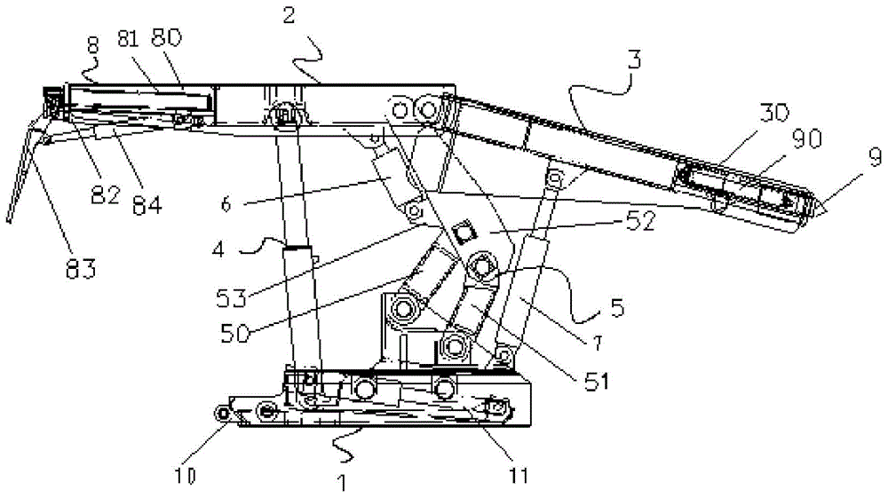
[0019] figure 1 It is a structural schematic diagram of the two-column transition hydraulic support of the present invention; figure 1 As shown, the two-column transition hydraulic support of the present invention includes: a base 1; a top beam 2 arranged above the base 1; a tail beam 3 hinged at one end of the top beam 2; a top beam supporting device installed on the base 1 , is connected with the top beam 2; the tail beam supporting device installed on the base 1 is connected with the tail beam 3. The below of the top beam 2 and the below of the tail beam 3 respectively form spaces for arranging the front and rear scraper heads and the tail driving parts.

[0020] Specifically, such as figure 1 As shown, the two-column transition hydraulic support of the present invention has a top beam 2, and one end of the top beam 2 is hinged with a tail beam 3. A pair of columns 4 are symmetrically arranged front and back ( figure 1 One column 4 shown in will cover the other column s...


PUM


Abstract

The invention discloses a double column-type transition hydraulic support, comprising a base (1), a top beam (2) arranged above the base (1), a tail beam (3) of which one end is hinged to one end of the top beam (2), and a front beam (8) fixed to the other end of the top beam (2). The double column-type transition hydraulic support is characterized by also comprising a top beam support device installed on the base (1), and a tail beam support device installed on the base (1), wherein the top beam support device is hinged to the top beam (2); the tail beam support device is hinged to the tail beam (3). The stability of the support is good, the utilization rate of resistance of the support can be improved, and the requirement for the installation space for a drive part of the head or tail of a front-back scraper machine can be met.

Description

technical field [0001] The invention relates to the technical field of coal mine support, in particular to a two-column transitional hydraulic support. Background technique [0002] When the two-column hydraulic support in the prior art is used as a transition hydraulic support, due to the small rear space in the structure, it cannot accommodate the installation of the front and rear scraper machine heads and tail drive parts, so the two-column hydraulic support can only It is used as an intermediate bracket (also called a basic frame), but not a transition frame. In addition, the force on the front and rear columns of the four-column transitional hydraulic support is unbalanced. Often, the force on the two rear columns is large, so that the second half of the bracket is crushed to death, resulting in a height lower than the required height at the rear of the bracket, while the front two columns are stressed. The force is small and the front part of the bracket is much high...

Claims


Application Information

Patent Timeline
Patent Type & Authority Applications(China)
IPC IPC(8): E21D23/04E21D23/16
CPCE21D23/04E21D23/16
Inventor 谢俊文卢熹李海宁李惠上官科峰关俊文杨世杰柳金辉李汉汉周冠骥刘瑜鑫
Owner HUATING COAL GRP
Why Eureka
Try Eureka