High-efficiency noise reducing and refrigerating compressor

A refrigeration compressor and noise reduction technology, applied in the field of refrigeration compressors, can solve the problems of reducing production cost, high cost, complex structure, etc., to strengthen the effect of noise reduction and vibration reduction, reduce noise and vibration, and improve the noise reduction effect. Effect

Inactive Publication Date: 2015-06-10
WUHU ABAUR MECHANICAL & ELECTRICAL
View PDF8 Cites 4 Cited by
  • Summary
  • Abstract
  • Description
  • Claims
  • Application Information

AI Technical Summary

Problems solved by technology

[0002] The existing silencing structure of refrigeration compressors is a plurality of silencing cylinders arranged on the cylinder block, the structure of this silencing structure is complicated, there are many parts, and the cost is high
The patent document with the publication number CN 201934284 disclosed on August 17, 2011 a compressor cylinder block with a horizontal integral silencer chamber, which uses an exhaust silencer chamber, and the refrigerant enters the silencer chamber from the upper part of the silencer chamber or The exhaust hole on the side is discharged; this technology simplifies the noise reduction structure and reduces the production cost. Since this patent document does not disclose the refrigerant exhaust flow direction, it is difficult to achieve a smooth exhaust flow path of the compressor, and only the cylinder block casting is used for noise reduction. , it is difficult to achieve a better noise reduction and vibration reduction effect

Method used


Image

  • High-efficiency noise reducing and refrigerating compressor
  • High-efficiency noise reducing and refrigerating compressor
  • High-efficiency noise reducing and refrigerating compressor

Examples


Embodiment Construction

[0030] The specific implementation manner of the present invention will be described in further detail below by describing the best embodiment with reference to the accompanying drawings.

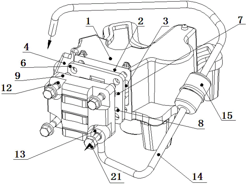
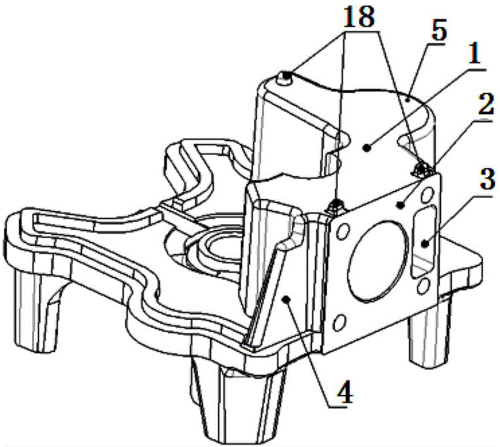
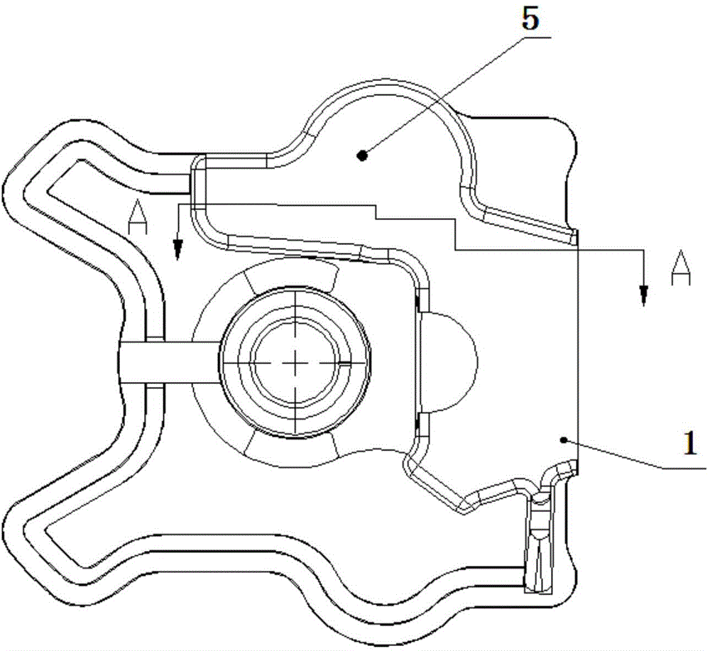
[0031] like Figure 1-Figure 6 As shown, the high-efficiency noise-reducing refrigeration compressor includes a cylinder block 1, and the cylinder block 1 is provided with an anechoic cavity 5, and the anechoic cavity 5 is arranged on one side of the front end of the cylinder block 1, and the anechoic cavity 5 is cast, and the front end surface of the cylinder block 2 There is an exhaust muffler chamber inlet 3 communicating with the muffler chamber 5; the front end of the cylinder block 1 is provided with a valve plate 6 and a cylinder head 9 connected to the cylinder base 1; The exhaust outlet 8; the cylinder head 9 is provided with an exhaust collection chamber 10 communicating with the exhaust outlet 8; the outlet 11 of the exhaust collection chamber 10 is provided with a secondary muff...


PUM


Abstract

The invention discloses a high-efficiency noise reducing and refrigerating compressor. The high-efficiency noise reducing and refrigerating compressor comprises a cylinder seat, wherein a noise elimination cavity is formed in the cylinder seat, and an inlet of an exhaust and noise elimination cavity, communicated with the noise elimination cavity, is formed in the end surface of the front end of the cylinder seat; a valve plate and a cylinder cover which are connected with the cylinder seat are arranged at the front end of the cylinder seat; an exhaust outlet communicated with the inlet of the exhaust and noise elimination cavity is formed in the valve plate; an exhaust and collection cavity communicated with the exhaust outlet is formed in the cylinder cover, a two-stage noise elimination mechanism is arranged at the outlet of the exhaust and collection cavity; after a refrigerant enters the noise elimination cavity from the exhaust and noise elimination cavity and noise elimination is performed, the refrigerant enters the exhaust and collection cavity of the cylinder cover from the exhaust outlet of the valve plate, and the exhaust and collection cavity has the effects of guide and buffering, so that the noise elimination effect and the vibration absorption effect are improved; the refrigerant enters the two-stage noise elimination mechanism from the outlet of the exhaust and collection cavity, and after the two-stage noise elimination is performed, the refrigerant is discharged, so that the purpose of high-efficiency noise reduction is achieved; besides, the high-efficiency noise reducing and refrigerating compressor disclosed by the invention is simple in the noise elimination and vibration absorption structure, simple in manufacture technology and lower in cost.

Description

technical field [0001] The invention relates to refrigeration compressor technology, in particular to a high-efficiency noise-reducing refrigeration compressor. Background technique [0002] The existing silencing structure of the refrigeration compressor is a plurality of silencing cylinders arranged on the cylinder block. The structure of this silencing structure is complicated, there are many parts, and the cost is relatively high. The patent document with the publication number CN 201934284 disclosed on August 17, 2011 a compressor cylinder block with a horizontal integral silencer chamber, which uses an exhaust silencer chamber, and the refrigerant enters the silencer chamber from the upper part of the silencer chamber or The exhaust hole on the side is discharged; this technology simplifies the noise reduction structure and reduces the production cost. Since this patent document does not disclose the refrigerant exhaust flow direction, it is difficult to achieve a smoo...

Claims


Application Information

Patent Timeline
Patent Type & Authority Applications(China)
IPC IPC(8): F04B39/00
Inventor 林银坤何景云江志安张文芳王世林何进王素彬张小利邹敏王丙银
Owner WUHU ABAUR MECHANICAL & ELECTRICAL
Why Eureka
Try Eureka