Fluid control valve and application thereof

A technology for controlling valves and valves, applied in safety valves, balance valves, valve devices, etc., can solve problems such as inconvenient operation, outlet blockage, fluid volatilization, etc., and achieve the effects of being convenient to carry out, isolating air exchange, and preventing liquid volatilization

Inactive Publication Date: 2015-06-10
SHANGHAI PINYI IND DESIGN
View PDF0 Cites 5 Cited by
  • Summary
  • Abstract
  • Description
  • Claims
  • Application Information

AI Technical Summary

Problems solved by technology

[0003] 1. Existing mainstream control valves, such as push valves, do not completely isolate the passage between the fluid in the container and the outside air, resulting in problems such as fluid volatilization or air oxidation;
[0004] 2. The pipeline between the control valve and the fluid outlet of the existing mainstream control valve fluid is long, and the remaining fluid in the pipeline will still flow slowly and dry up after the valve is closed, and the outlet will be blocked if it is not used for a long time;
[0005] 3. Existing mainstream valves, such as push-type valves, cannot fully discharge the fluid in the container, resulting in more fluid remaining in the container, resulting in waste of resources and environmental pollution;
[0006] 4. The existing mainstream valve body structure is relatively complex, and the manufacturing cost and maintenance cost are relatively high;
[0007] 5. For containers without mainstream control valves, in actual use, due to improper control of the hand feel, the fluid is used too much or too little, and the amount of single use cannot be better controlled, and the operation is inconvenient;
For example, the push-type discharge valve of body wash and shampoo does not isolate the contact between liquid and air. When the air is dry, dry solid matter will be formed at the outlet in about 5 days. After use, about 5% of the residue cannot be discharged, resulting in waste and pollution happen
Edible oil and soy sauce are still used in the traditional method of opening the cover → dumping → closing the cover, which is not convenient enough to operate and difficult to control the dosage

Method used


Image

  • Fluid control valve and application thereof
  • Fluid control valve and application thereof
  • Fluid control valve and application thereof

Examples


Embodiment Construction

[0030] The present invention will be further described below in conjunction with accompanying drawing, and the structure and principle of this device are very clear to those skilled in the art. It should be understood that the specific implementation cases described here are only used to explain the present invention, and are not intended to limit the present invention.

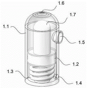
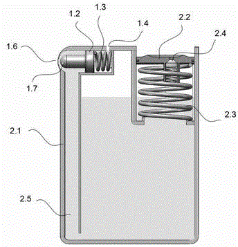
[0031] 1. The working principle of the valve body: figure 1 Shown: Under normal conditions, the valve body spring 1.3 is only affected by the elastic force of the spring, pushing the piston 1.2 and the spherical valve body 1.7 to close the valve body outlet 1.6. When the fluid enters the valve body cavity through the fluid inlet 1.5, as the pressure increases, The pressure of the fluid on the piston is also increasing. When the fluid pressure is greater than the spring force, the piston is pushed to open the spherical valve, and the fluid flows out through the outlet of the valve body. When the pressure conti...


PUM


Abstract

The invention relates to the field of fluid control valves, in particular to a novel control valve and application thereof. The structure of a valve body is shown as figure 1 and comprises a spring and a piston. In a normal state, under the push force of a spring 1.3 of the valve body, a spherical valve 1.7 and a fluid outlet 1.6 are in a closed state; after a pressure storage fluid enters the cavity of the valve body through a fluid inlet 1.5, the pressure on a piston can be increased; after the pressure of the fluid is greater than the elastic force subjected to the piston, the piston drives the spherical valve 1.7 to open the fluid outlet 1.6; when the pressure of the fluid in the cavity is lower than the elastic force of the spring of the valve body, the spring resets to push the spherical valve 1.7 and the fluid outlet 1.6 to close. An air circulating hole 1.4 is communicated to an atmosphere layer. The strength required to open the spherical valve is decided by the stiffness coefficient of the spring; springs with different stiffness coefficients can be selected according to the pressure of the fluid, so that the valve body can be widely applied to the field of automatic control of various fluids.

Description

technical field [0001] The invention relates to the field of fluid control, in particular to a fluid control valve and some applications thereof. Background technique [0002] In the current application of fluid control valves: chemical industry, chemical experiments, daily life and many other aspects, the existing fluid control methods have the following problems: [0003] 1. Existing mainstream control valves, such as push valves, do not completely isolate the passage between the fluid in the container and the outside air, resulting in problems such as fluid volatilization or air oxidation; [0004] 2. The pipeline between the control valve and the fluid outlet of the existing mainstream control valve fluid is long, and the remaining fluid in the pipeline will still flow slowly and dry up after the valve is closed, and the outlet will be blocked if it is not used for a long time; [0005] 3. Existing mainstream valves, such as push-type valves, cannot fully discharge the ...

Claims


Application Information

Patent Timeline
Patent Type & Authority Applications(China)
IPC IPC(8): F16K17/04F16K17/168F16J12/00
CPCF16J12/00F16K17/04F16K17/168
Inventor 李晓庆
Owner SHANGHAI PINYI IND DESIGN
Why Eureka
Try Eureka