Supercharge Your Innovation With Domain-Expert AI Agents!

Novel controller for pneumatic butterfly valve

A pneumatic butterfly valve and controller technology, applied in valve details, valve devices, engine components, etc., can solve the problems of operation control relying on industrial control equipment and systems, installation and debugging level in limited use environments, affecting the service life of solenoid valves, etc. Simple structure, beautiful appearance and reasonable layout

Inactive Publication Date: 2015-06-10
HANGZHOU SAIMIKE VALVE MFG
View PDF9 Cites 1 Cited by
  • Summary
  • Abstract
  • Description
  • Claims
  • Application Information

AI Technical Summary

Problems solved by technology

[0003] For a long period of time, domestic inflatable sealing special valves have been monopolized by foreign products. Foreign brand inflatable butterfly valves headed by American Aerodynamics have occupied almost all pipelines and pumps in pneumatic conveying. Due to the operation of these brand valves The control is heavily dependent on the user's industrial control equipment and system, and is limited by the user's actual use environment and the level of installation and debugging of the workers. Up to 70% of the damage is caused by the control system - that is, 70% of the service life of the valve Worn out from abnormal early wear and damage
[0004] The solenoid valve of the existing pneumatic butterfly valve controller generally only controls the action gas path of the pneumatic actuator; moreover, the solenoid valve and the air pipe joint are generally directly exposed, which is not only inconvenient to disassemble, the structure layout is not reasonable, but also affects the service life of the solenoid valve , thus increasing the maintenance cost

Method used


Image

  • Novel controller for pneumatic butterfly valve
  • Novel controller for pneumatic butterfly valve
  • Novel controller for pneumatic butterfly valve

Examples


Embodiment Construction

[0020] The present invention will be described in further detail below in conjunction with the accompanying drawings, but it is not intended to limit the protection scope of the present invention.

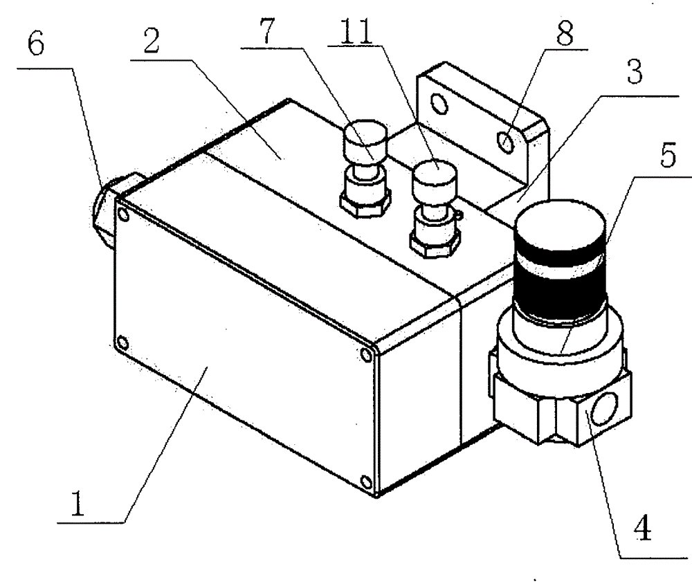
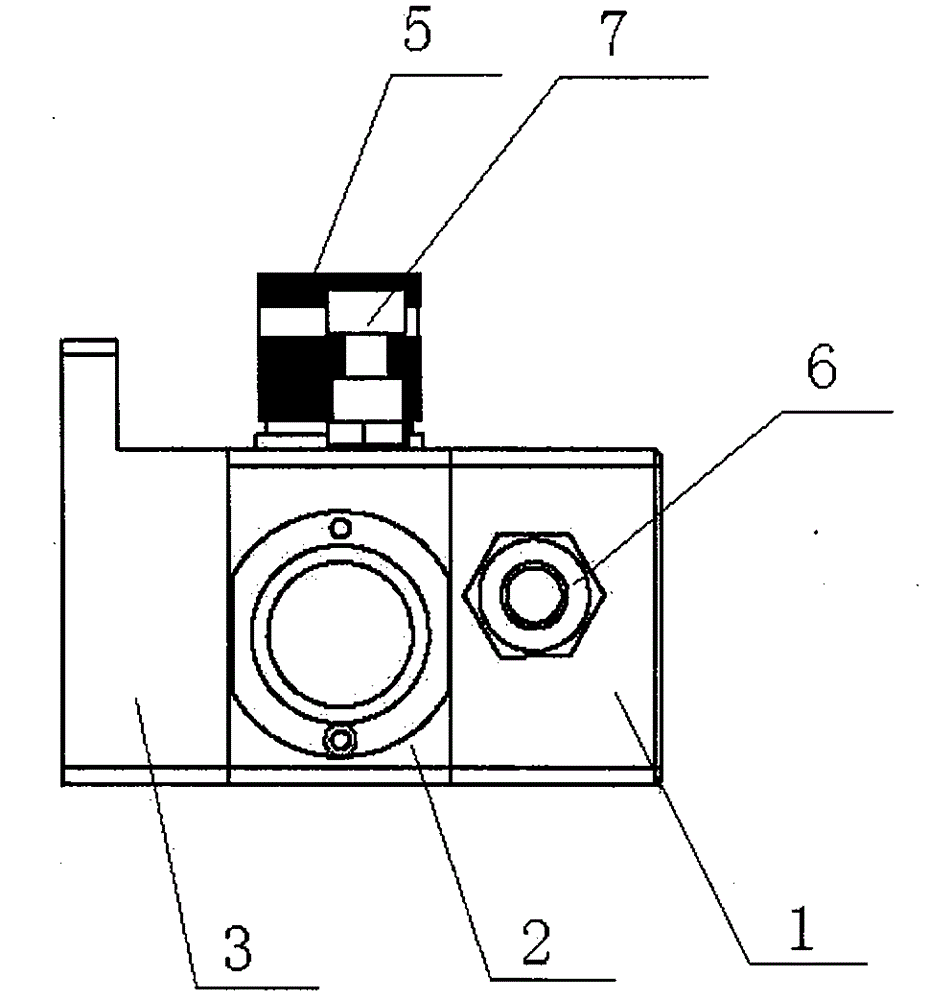
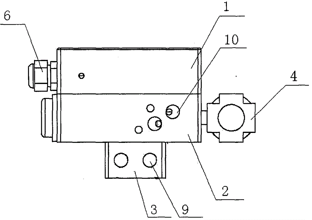
[0021] like Figure 1-3 As shown, a novel pneumatic butterfly valve controller includes a casing, a gas source connector 4 and a gas outlet arranged on the casing, and a solenoid valve 12 arranged in the casing. The gas outlet includes a first gas connected to a pneumatic actuator. The outlet 9 and the second gas outlet 10 connected to the elastic valve seat, the air source connection head 4 is provided with an air pressure reducing valve 5, the air source connection head 4 is connected with the solenoid valve 12, and the solenoid valve 12 is respectively connected with the first gas outlet 9 and The second gas outlet 10 is connected. The casing includes a first casing 1 and a second casing 2 that communicate with each other, the second casing 2 is provided with a mounting casing ...


PUM


Abstract

The invention relates to a controller, particularly to a novel controller for a pneumatic butterfly valve. The controller comprises a casing, an air source connector and air outlets which are arranged on the casing as well as a solenoid valve arranged in the casing, wherein the air outlets comprise a first air outlet connected with a pneumatic actuator and a second air outlet connected with an elastic valve seat, an air pressure relief valve is arranged at the air source connector, the air source connector is connected with the solenoid valve, and the solenoid valve is connected with the first air outlet and the second air outlet respectively. According to the controller, the solenoid valve and multiple air pipe joints are arranged in the casing, so that the controller is simple in structure, reasonable in arrangement, convenient to mount and dismount and attractive in appearance; meanwhile, the solenoid valve is connected with the first air outlet and the second air outlet respectively, so that an action air path of the pneumatic actuator and an inflation air path of the elastic valve seat can be controlled by the solenoid valve, abrasion during opening and closing of a valve disc and the valve seat can be reduced, and the sealing performance during closing of the valve disc and the valve seat can also be guaranteed.

Description

technical field [0001] The invention relates to a controller, in particular to a novel pneumatic butterfly valve controller. Background technique [0002] Butterfly valve control system, or butterfly valve controller, is an electrical integration component specially serving pneumatic inflatable butterfly valves and dome valves. It can form its own logic to ensure the correct switching action and service life of the valve to the greatest extent. [0003] For a long period of time, domestic inflatable and sealed special valves have been monopolized by foreign products. Foreign brand inflatable butterfly valves led by American Aerodynamics occupy almost all pipelines and pump warehouses of pneumatic conveying. Due to the operation of these brand valves The control depends heavily on the user's industrial control equipment and systems, and is limited by the user's actual use environment and the level of installation and commissioning of workers. Up to 70% of the damage is caused...

Claims


Application Information

Patent Timeline
Patent Type & Authority Applications(China)
IPC IPC(8): F16K31/12
CPCF16K31/12
Inventor 应卫龙徐海燕
Owner HANGZHOU SAIMIKE VALVE MFG
Features
  • R&D
  • Intellectual Property
  • Life Sciences
  • Materials
  • Tech Scout
  • Unparalleled Data Quality
  • Higher Quality Content
  • 60% Fewer Hallucinations
Learn More