Runway light for airport

An airport runway and lighting technology, applied in the field of lighting, can solve the problems of large installation space, increase the overall size and production cost of runway lights, and cannot meet the needs of special airport runways, meet the requirements of light distribution design, and improve light energy. The effect of utilization

Inactive Publication Date: 2015-06-10
SHENZHEN OCEANS KING LIGHTING ENG CO LTD +1
View PDF0 Cites 0 Cited by
  • Summary
  • Abstract
  • Description
  • Claims
  • Application Information

AI Technical Summary

Problems solved by technology

However, the existing airport runway lights have the following disadvantages: (1) The structural size of the reflector is often large, which will occupy a large installation space, resulting in an increase in the overall size and production cost of the runway lights; (2) The reflectivity of the reflector is low, generally only about 80%, resulting in a large loss of light energy and a low utilization rate of light energy
Therefore, the existing runway lights cannot meet the actual needs, especially the needs of special-purpose airport runways (such as military airport runways)

Method used


Image

  • Runway light for airport
  • Runway light for airport
  • Runway light for airport

Examples


Embodiment Construction

[0021] The following will clearly and completely describe the technical solutions in the embodiments of the present invention with reference to the accompanying drawings in the embodiments of the present invention. Obviously, the described embodiments are only some, not all, embodiments of the present invention. Based on the embodiments of the present invention, all other embodiments obtained by persons of ordinary skill in the art without creative efforts fall within the protection scope of the present invention.

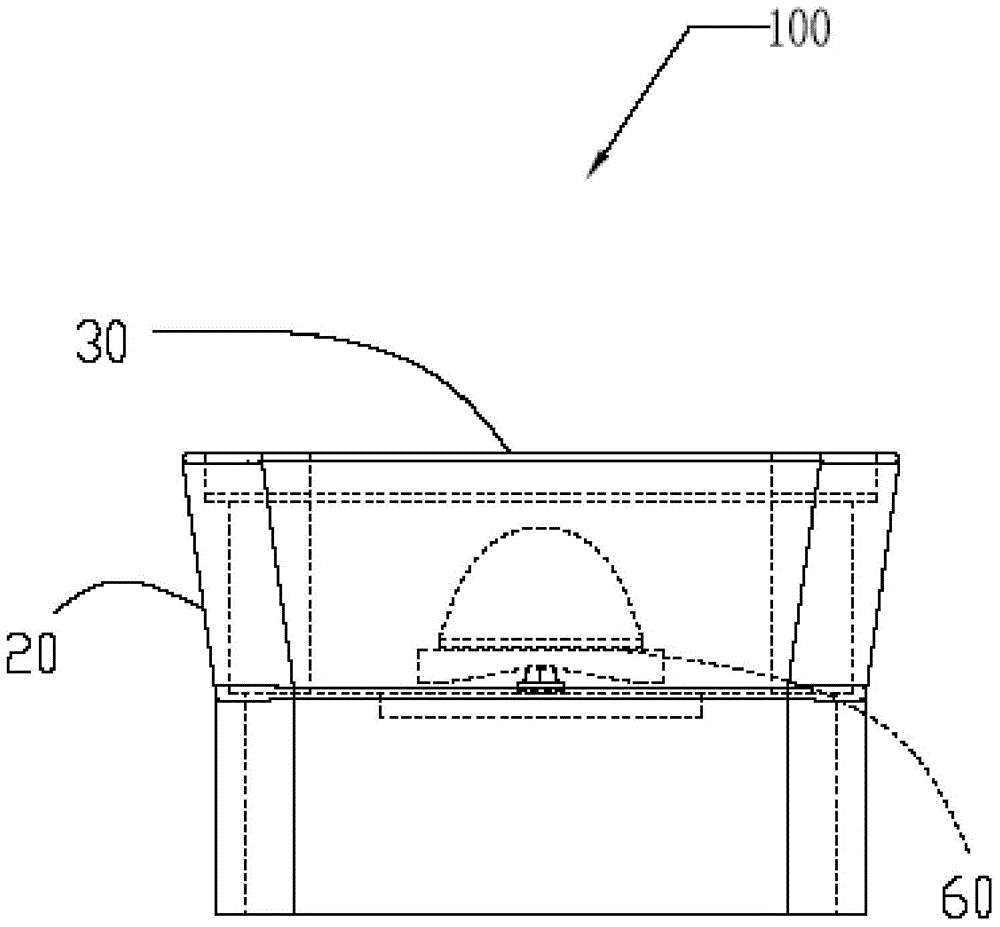
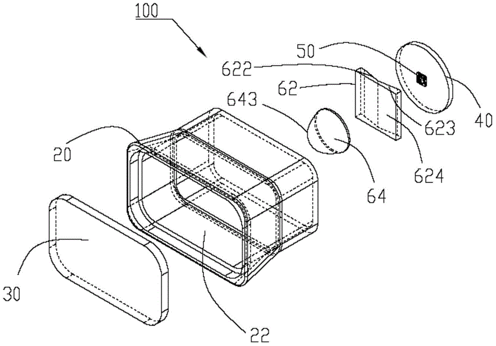
[0022] see figure 1 and figure 2 , the embodiment of the present invention provides an airport runway light 100, which is used as an airport navigation aid lighting fixture, which is installed on both sides of the airport runway and at both ends of the runway to indicate the position and range of the runway. In the embodiment of the present invention, the The airport runway lights 100 are illustrated by taking runway end lights as an example. The airport runway ...


PUM


Abstract

The invention relates to a runway light for an airport. The runway light for the airport comprises a housing component and a light source and a lens component arranged in the housing component, wherein the lens component comprises a first lens and a second lens; the first lens comprises a first incident plane, a second incident plane and a first ray exit surface; the light source is aligned with the first incident plane and the second incident plane; included angles are formed between the first incident plane and the second incident plane and the plane perpendicular to the optical axis of the light source and are symmetrical around the plane perpendicular to the optical axis; the second lens is mounted on the first ray exit surface and comprises a third incident plane and a second ray exit surface; light emitted by the light source refracted by the first incident plane and the second incident plane is scattered and irradiated to the second ray exit surface through the first ray exit surface and the third incident plane, and is refracted on the ray exit surface to form a gathered light which is ejected.

Description

technical field [0001] The invention relates to the field of lighting, in particular to an airport runway light. Background technique [0002] Airport runway lights are used as airport navigation lighting fixtures, which are lighting equipment installed along both sides of the airport runway and at both ends of the runway to indicate the position and range of the runway. According to different installation methods, these runway lights are divided into vertical lights and recessed lights, and most of them use traditional halogen lamps as light sources. In actual use, most of these runway lights use reflectors to gather light. However, the existing airport runway lights have the following disadvantages: (1) The structural size of the reflector is often large, which will occupy a large installation space, resulting in an increase in the overall size and production cost of the runway lights; (2) The reflectivity of the reflector is relatively low, generally only about 80%, whic...

Claims


Application Information

Patent Timeline
Patent Type & Authority Applications(China)
IPC IPC(8): F21V5/04F21S8/00F21V29/70F21W111/06F21Y101/02F21Y115/10
CPCF21S8/00F21V5/048F21W2111/06
Inventor 周明杰黄俊晖
Owner SHENZHEN OCEANS KING LIGHTING ENG CO LTD
Why Eureka
Try Eureka