Sound-wave dust-blowing device

A technology of soot blowing device and sound wave, applied in the field of soot blowing device, can solve the problems of high load of rotating shaft bearing, easy to wear turntable, unstable wind shear, etc., and achieve the effect of prolonging life, reducing wear and improving stability

Inactive Publication Date: 2015-06-10
TIANJIN HANGWOTE MACHINERY MFG
View PDF0 Cites 6 Cited by
  • Summary
  • Abstract
  • Description
  • Claims
  • Application Information

AI Technical Summary

Problems solved by technology

[0003] The present invention solves the problem that when the turntable of the existing sonic soot blower rotates, the bearing of the rotating shaft bears a higher load due to the chang

Method used


Image

  • Sound-wave dust-blowing device
  • Sound-wave dust-blowing device
  • Sound-wave dust-blowing device

Examples


specific Embodiment approach 1

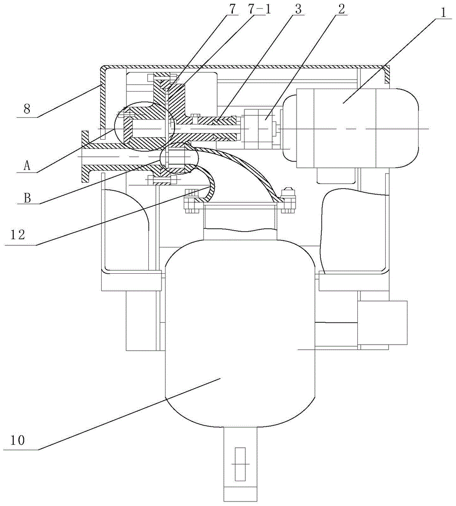
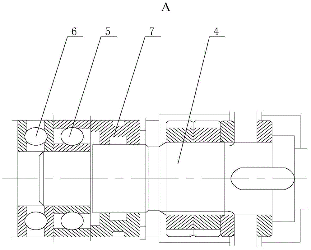
[0010] Specific implementation mode one: combine figure 1 , figure 2 and image 3 Describe this embodiment, a sonic soot blowing device described in this embodiment includes a driving mechanism, a transmission shaft 4, a rotary bearing 5, a thrust bearing 6, a turntable 7, a casing 8 and an air blowing mechanism, and the driving mechanism is installed in the casing In the upper part of the body 8, one end of the transmission shaft 4 is connected to the drive mechanism, and the turntable 7, the rotary bearing 5, and the thrust bearing 6 are sequentially set on the transmission shaft 4 from one end to the other end of the transmission shaft 4, and the turntable 7 is evenly arranged with A plurality of air holes 7-1, the blowing mechanism is installed in the casing 8, and the air holes 7-1 on the turntable 7 are tangent to the airflow generated by the blowing mechanism.

specific Embodiment approach 2

[0011] Specific implementation mode two: combination figure 1 and figure 2 Describe this embodiment, the driving mechanism of a sonic soot blowing device described in this embodiment includes a motor 1, a frequency converter 2 and a coupling 3, the frequency converter 2 is connected to the motor 1, and the rotating shaft of the motor 1 passes through the coupling 3 Connect with one end of transmission shaft 4. Other components and connections are the same as those in the first embodiment.

specific Embodiment approach 3

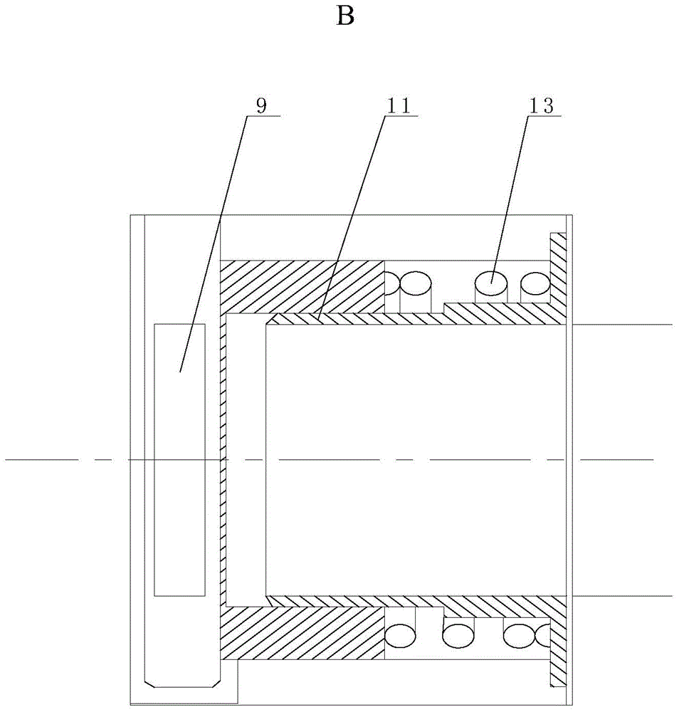
[0012] Specific implementation mode three: combination figure 1 and figure 2 Describe this embodiment, the air blowing mechanism of a kind of sound wave soot blowing device described in this embodiment includes air blowing pipe 9, air tank 10, air supply pipe 11 and sonic air flow horn line pipe 12, the air outlet of air tank 10 and the sonic air flow horn The air inlet of the line pipe 12 is connected, the air outlet of the sound wave airflow horn line pipe 12 is connected with one end of the air blowing pipe 9 through the air supply pipe 11, the other end of the air blowing pipe 9 passes through the casing 8 to leak out, and the edge of the turntable 7 is inserted At the junction of the air supply pipe 11 and the air blow pipe 9 , the air hole 7 - 1 on the turntable 7 is tangent to the airflow in the air supply pipe 11 and the air blow pipe 9 . Other components and connections are the same as those in the first embodiment.


PUM


Abstract

The invention relates to a dust-blowing device, in particular to a sound-wave dust-blowing device, and aims to solve the problem of instable wind shear, which is caused by the fact that when a rotating disc of the existing sound-wave dust blower rotates, due to change of airflow pressure, a bearing of a rotating shaft bears a relatively high load, is easily abraded and generates rotary swing of the rotating disc. The sound-wave dust-blowing device comprises a driving mechanism, a transmission shaft, a rotating bearing, a thrust bearing, a rotating disc, a housing and a blowing mechanism, wherein the driving mechanism is mounted at the upper part inside the housing; one end of the transmission shaft is connected with the driving mechanism; the rotating disc, the rotating bearing and the thrust bearing sequentially sleeve the transmission shaft from one end to the other end of the transmission shaft; a plurality of air holes are uniformly formed in the rotating disc; the blowing mechanism is mounted inside the housing; the air holes in the rotating disc are tangent to an airflow generated by the blowing mechanism. The sound-wave dust-blowing device is used for cleaning dust, rust, oxide skin and the like on a furnace wall.

Description

【Technical field】 [0001] The present invention relates to a soot blowing device, more particularly, to an acoustic wave soot blowing device. 【Background technique】 [0002] The sonic soot blower is based on the electric energy to drive the motor to rotate to generate mechanical energy to rotate the transmission turntable. The wind holes on the turntable and the air flow passing through form a wind shear, and then the wind shear generates sound waves, which cause dust, rust, and oxidation through the transmission of sound wave energy. The air in the gap area physically adhered between the skin and the pipe wall resonates, and the sound wave pressure acts on the ash layer, rust, and oxide skin to generate air pressure thrust, and then automatically separates from the pipe wall to achieve the removal and cleaning effect. The sonic soot blower is mainly used to remove dust, rust, scale, etc. on the furnace wall. When the turntable of the existing sonic soot blower rotates, the b...

Claims


Application Information

Patent Timeline
IPC IPC(8): F23J1/00F23J3/00
Inventor 颜昭奇
Owner TIANJIN HANGWOTE MACHINERY MFG
Why Eureka
Try Eureka