
Oscillatory wave system

A technology of oscillating waves and oscillators, applied in the field of partial discharge detection systems, can solve problems affecting the use of the system, and achieve the effects of avoiding internal discharge, good linearity, and avoiding interference

Active Publication Date: 2015-06-10
STATE GRID SHANDONG ELECTRIC POWER +1
View PDF6 Cites 3 Cited by
  • Summary
  • Abstract
  • Description
  • Claims
  • Application Information

AI Technical Summary

Problems solved by technology

[0009] For this reason, what the present invention aims to solve is the technical problem that the partial discharge of the inductance in the existing oscillatory wave detection system affects the use effect of the system, and provides an oscillatory wave system including improved inductance

Method used


Image

  • Oscillatory wave system
  • Oscillatory wave system
  • Oscillatory wave system

Examples


Embodiment approach

[0084] As a specific embodiment of the present invention, the working sequence diagram of the high-voltage electronic switch control signal, the high-voltage electronic switch opening situation, the optical MOS relay control signal and the optical MOS relay opening situation can be found in Figure 5 As shown, when the base of the triode Q is at a high level, the triode Q is turned on, Vcc forms a circuit through the first resistor R1 and the infrared light-emitting diode inside the relay, the light-emitting diode is bright, and the photodiode array converts the light into an electrical signal. Control the conduction of the MOS tube, which is manifested as the "pulling in" of the relay, that is, the switch of the optical MOS solid state relay is closed.

[0085] Through the expansion of the transistor Q and the indirect control of the opening of the optical MOS solid-state relay, the base of the transistor Q only needs a microampere current to control the operation of the trans...


PUM


Abstract

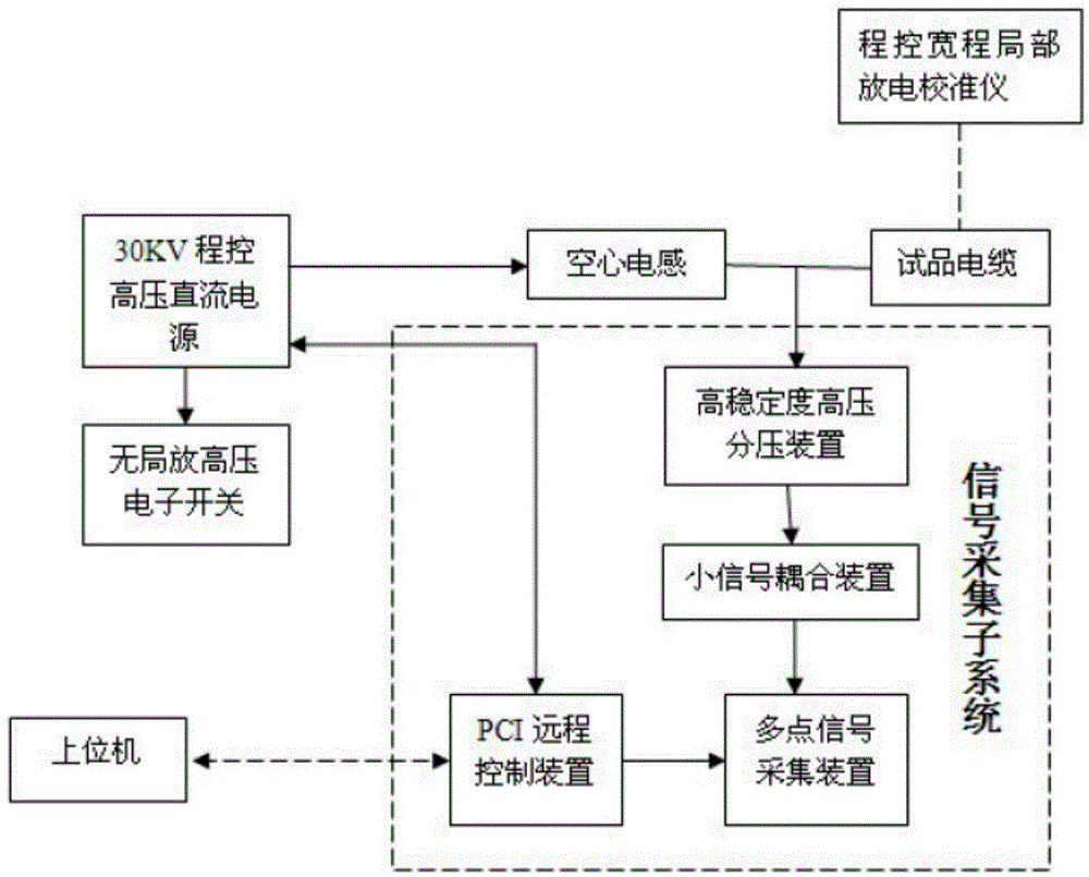
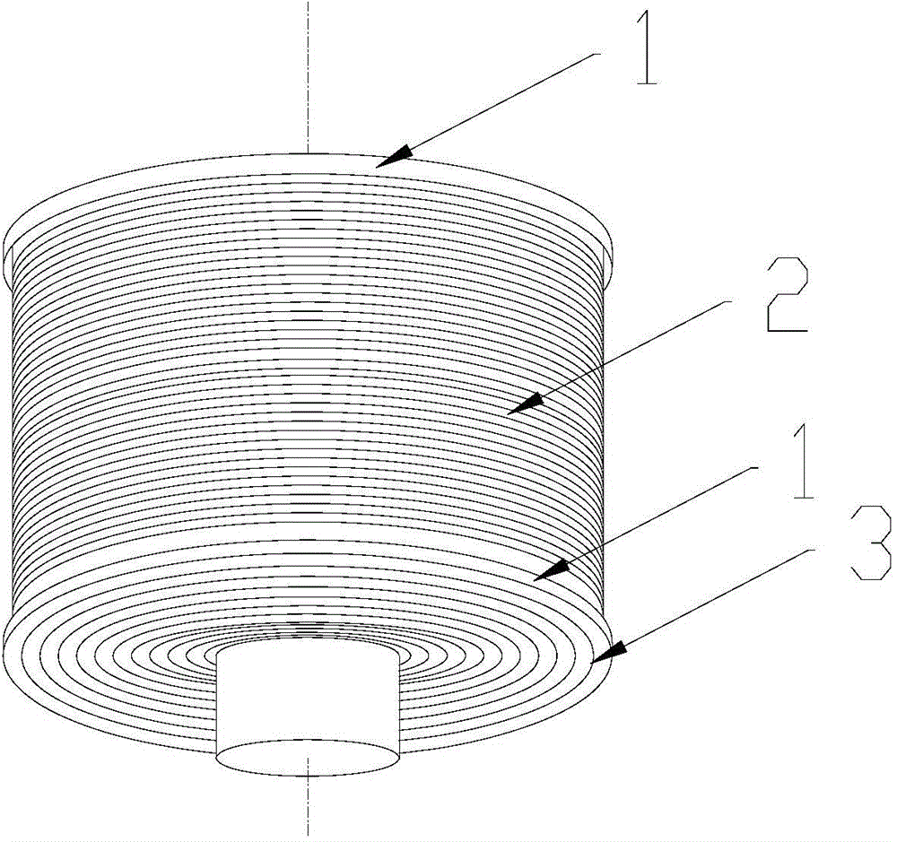
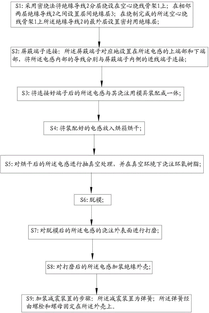
The invention relates to an oscillatory wave system. The oscillatory wave system comprises a cable to be detected, an oscillator generation device, a signal collection system and an IPC (industrial personal computer), wherein a hollow inductor in the oscillator generation device comprises a hollow coiling skeleton, an insulation guide wire is wound around the hollow coiling skeleton in layering mode, an interlayer insulation layer is arranged between each two adjacent layers of the insulation guide wire, an insulation layer for sealing is arranged on the outermost layer of the insulation guide wire on the hollow coiling skeleton, shield terminals are respectively arranged on the upper end portion and the lower end portion of the hollow inductor, and used to draw forth the insulation guide wire in the hollow inductor, and an insulation shell is used to seal the hollow inductor. According to the oscillatory wave system, each interlayer insulation layer is arranged between each two adjacent layers of the insulation guide wire, insulation intervals are guaranteed, a discharging or corona phenomenon is prevented from occurring in the hollow inductor, partial discharging is prevented during the use process, normal detection of the oscillatory wave system is guaranteed, and adjacent turns of the insulation guide wire on each layer are tightly arranged without an interval, and the size and the weight of the hollow inductor are further reduced.

Description

[0001] This application is a divisional application with application number 201210594359.7; [0002] The filing date of the original application is: December 31, 2012; [0003] The invention title of the original application is: oscillatory wave system. technical field [0004] The invention relates to a partial discharge detection system, in particular to an oscillatory wave system. Background technique [0005] In the past ten years, extruded power cables, especially cross-linked polyethylene (XLPE) power cables, have been widely used in urban power grids due to their good insulation performance, easy manufacturing, convenient installation, and safe and reliable power supply. However, in the insulation structure of this kind of cable, there are often air gaps and harmful impurities due to the difficulty of processing technology or the impurity of raw materials, or there are gaps or semi-conductive conductors between the insulating medium and the semi-conductive shielding ...

Claims


Application Information

Patent Timeline
Patent Type & Authority Applications(China)
IPC IPC(8): G01R31/12G01R31/14
Inventor 时翔赵生传陈志勇江川潘滨蔡健牟磊崔潇蓝先明李志戈艾福超刘术波张宏伟陈永平
Owner STATE GRID SHANDONG ELECTRIC POWER
Learn More