Intensive type DC de-icing device topology structure

A technology of DC ice melting and topological structure, which is applied in the direction of circuit devices, harmonic reduction devices, overhead installations, etc., can solve the problems of heavy operation and maintenance workload, low utilization rate of ice melting devices, and low operation reliability, and achieve simplification The device topology design, the realization of device function expansion, and the effect of improving operation reliability

Active Publication Date: 2015-06-10
STATE GRID HUNAN ELECTRIC POWER +3
View PDF5 Cites 15 Cited by
  • Summary
  • Abstract
  • Description
  • Claims
  • Application Information

AI Technical Summary

Problems solved by technology

[0003] A few universities and scientific research institutes at home and abroad have conducted some research on the multifunctional topology of DC ice-melting devices. At present, the topological structure of DC ice-melting and SVC-type DC ice-melting devices is the main one. The devices developed with this topology have the following defects: Defects First, the operating harmonics are large, and a large number of filtering devices need to be added to the input side of the device. The heat generation is serious, and the power device needs to adopt a complex water cooling system; the second defect is that the device needs to be equipped with a large number of reactors to achieve capacitive reactive power and inductive power of equal capacity. Reactive power output, high cost, large floor area; defect three, complex device structure, heavy operation and maintenance workload, changing the functional operation mode of the device requires a large number of switching operations, low operational reliability, and poor SVC function expansion effect
Therefore, in view of the characteristics of the deicing and SVC type DC deicing device, combined with the functional requirements of the substation, it is urgent to develop an intensive deicing system with low operating harmonics, low calorific value, simple structure, high reliability, and can effectively improve the utilization rate of the device. Research on the topological structure of the ice device provides guidance for the structural design and final development of the device, so as to effectively solve the problem of low utilization rate of the ice melting device

Method used


Image

  • Intensive type DC de-icing device topology structure

Examples


Embodiment Construction

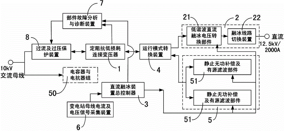
[0019] figure 1 Shown is an embodiment of the topology of the intensive DC ice-melting device integrating reactive power compensation and active filtering in the present invention, which can realize 12.5kV DC voltage output, and its DC ice-melting capacity is 25MW, and the static reactive power compensation capacity It is ±15Mvar, and can actively filter the 13th and below low-order harmonics. will be combined below figure 1 The present invention will be described in detail with reference to the illustrated embodiments.

[0020] Such as figure 1 As shown, the topological structure of the intensive DC ice-melting device in this embodiment includes a constant-impedance low-loss connection transformer 1, an ice-melting branch 2 and a general controller 3 of the DC ice-melting device. The control terminal of the ice-melting branch 2 is connected to the DC melting The main controller 3 of the ice plant is connected, and the topology structure also includes an operation mode conv...


PUM


Abstract

The invention discloses an intensive type DC de-icing device topology structure. The intensive type DC de-icing device topology structure comprises a constant impedance low-loss connection transformer, a de-icing branch, a DC de-icing device main controller, an operation mode transformation device, a reactive compensation and active filter branch and a transformer substation bus current and voltage signal acquiring device; the transformer substation bus current and voltage signal acquiring device is connected with a DC de-icing device main controller; the control end of a static reactive compensation and active filter part is connected with the DC de-icing device main controller; the input end of the operation mode transformation mode is connected with an C bus of a transformer substation through the constant impedance low-loss connection transformer, and while the output end of the operation mode transformation mode is respectively connected with the de-icing branch and the reactive compensation and active filter branch. The intensive type DC de-icing device topology structure can perform de-icing, reactive compensation and active filter, and is reliable to run; the de-icing and the reactive compensating capacity can be independently configured; therefore, the guidance is provided for the multifunctional topology structure of the de-icing device; the intensive type DC de-icing device topology structure can be widely applied to various transformer substations.

Description

technical field [0001] The invention relates to the technical field of electrical engineering, in particular to a topological structure of an intensive DC deicing device. Background technique [0002] The DC ice melting device provides an effective ice melting method for the transmission line to deal with ice disasters, but the DC ice melting device is only used when the line is covered with ice in winter, the utilization rate is low, and the long-term use of the device is easy to cause equipment damage, and there are many problems in operation. big security risk. Therefore, under the premise of ensuring the simple structure of the ice-melting device and the reliable operation of the ice-melting device, it is of great technical and economic value to carry out research on the topology structure that can realize the function expansion of the ice-melting device and improve the utilization rate of the ice-melting device. [0003] A few universities and scientific research insti...

Claims


Application Information

Patent Timeline
Patent Type & Authority Applications(China)
IPC IPC(8): H02G7/16H02J3/18H02J3/01
CPCH02G7/16H02J3/01H02J3/1807Y02E40/30Y02E40/40
Inventor 陆佳政朱思国李波方针张红先
Owner STATE GRID HUNAN ELECTRIC POWER
Why Eureka
Try Eureka