Micro-grid system monitoring device capable of automatically achieving frequency control

A monitoring device and frequency control technology, applied in circuit devices, photovoltaic power generation, wind power generation, etc., can solve the problems of small active power regulation capacity of the power grid and weak power grid construction, so as to prolong the service life, ensure safety, and take into account the reliability of power supply sexual effect

Inactive Publication Date: 2015-06-10
CHENGDU DINGZHIHUI TECH
View PDF5 Cites 7 Cited by
  • Summary
  • Abstract
  • Description
  • Claims
  • Application Information

AI Technical Summary

Problems solved by technology

When wind power is connected to the grid, especially for small grids that operate independently, the grid construction is relatively weak, and the grid’s active power adjustment capability is small, and the grid stability problems caused by wind power grid connection are more obvious

Method used


Image

  • Micro-grid system monitoring device capable of automatically achieving frequency control
  • Micro-grid system monitoring device capable of automatically achieving frequency control
  • Micro-grid system monitoring device capable of automatically achieving frequency control

Examples


Embodiment Construction

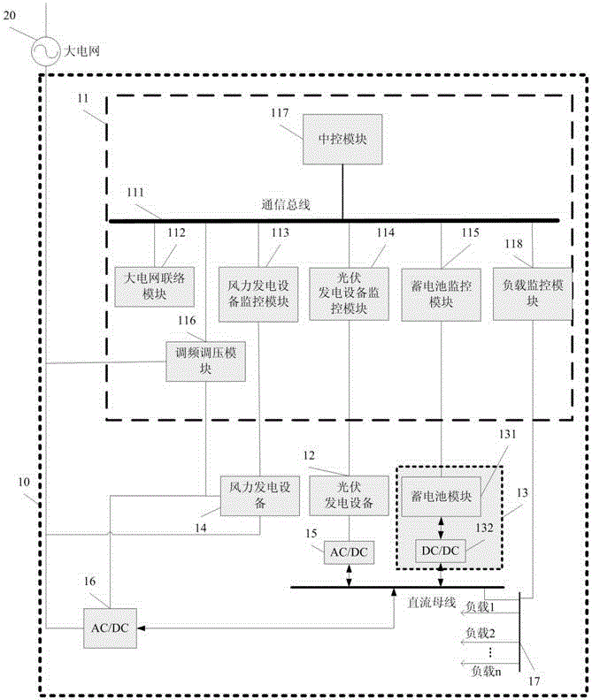
[0028] figure 1 It shows a microgrid 10 with an energy storage system capable of stabilizing power fluctuations according to the present invention. The microgrid 10 includes: a photovoltaic power generation device 12, an energy storage system 13, a wind power AC / DC bidirectional converter module 1 16 connected to and isolated from large grid 20 , DC bus, AC / DC bidirectional converter module 2 15 for connecting photovoltaic power generation equipment 12 and DC bus, load 17 and monitoring device 11 .

[0029] see figure 1 , the energy storage system 13 includes a battery module 131 and a bidirectional DC / DC converter 132 connected to the above-mentioned DC bus.

[0030] The monitoring device 11 includes: a photovoltaic power generation equipment monitoring module 114, used for real-time monitoring of the photovoltaic power generation equipment 12 in the battery energy storage system 10, and predicting the power generation power of the photovoltaic power generation equipment 12;...


PUM


Abstract

A monitoring device 11 comprises a photovoltaic power generation equipment monitoring module 114, an energy storage system monitoring module 115, a large power grid communicating module 112, a frequency and voltage modulating module 116, a center control module 117, a wind power generation equipment monitoring module 113, a load monitoring module 118 and a bus module 111. The photovoltaic power generation equipment monitoring module 114 is used for monitoring photovoltaic power generation equipment 12 in a battery energy storage system 10 in real time and predicting the generation power of the photovoltaic power generation equipment 12; the energy storage system monitoring module 115 is used for monitoring a storage battery module 131 and a DC/CD bidirectional transducer 132 in an energy storage system 13 in real time; the large power grid communicating module 112 is used for learning the running condition and relevant scheduling information of a large power grid 20 from a regulation and control center of the large power grid 20 in real time; the frequency and voltage modulating module 116 is used for controlling a micro-grid system 10 to participate in the frequency and voltage modulation of the large power grid 20 and comprises a frequency modulating module, a voltage modulating module and a cooperative control module; the center control module 117 is used for determining the running strategy of the micro-grid system 10 and giving instructions to all the modules to carry out the power supply strategy; the wind power generation equipment monitoring module 113 is used for monitoring wind power generation equipment 14 in real time; the load monitoring module 118 is used for monitoring loads 17 in the micro-grid system 10 in real time; the bus module 111 is used for the signal communication of each module in the monitoring device 11.

Description

Technical field [0001] The invention relates to a monitoring device for a micro-grid system that can automatically realize frequency control. Background technique [0002] Micro-grid (Micro-Grid), also translated as micro-grid, is a new type of network structure. It is a system unit composed of a group of micro-power sources, loads, energy storage systems and control devices. It can realize an autonomous system of self-control, protection and management. , it can run in parallel with the external power grid or run in isolation. [0003] As a supplement to the ultra-high voltage, long-distance, and large-grid power supply mode, the micro-grid based on wind power and photovoltaic power generation represents a new development direction of the power system. The driving force of wind turbines is wind energy. Due to the intermittent and random fluctuations of wind energy, the power generated by wind turbines is intermittent and fluctuating. The connection of these fluctuating win...

Claims


Application Information

Patent Timeline
Patent Type & Authority Applications(China)
IPC IPC(8): H02J3/46
CPCH02J3/32H02J3/383H02J3/386Y02E10/56Y02E10/76
Inventor 肖会
Owner CHENGDU DINGZHIHUI TECH
Why Eureka
Try Eureka