Wide-voltage-range LED (light emitting diode) lamp switching and dimming driving circuit and LED lamp dimming control system

A LED light, dimming drive technology, applied in the direction of electric light circuit layout, electric light source, light source, etc., can solve the problems of inability to adjust light, inconvenient operation, troublesome use, etc.

Active Publication Date: 2015-06-10
SHENZHEN ANDYSOM LIGHTING CO LTD
View PDF4 Cites 11 Cited by
  • Summary
  • Abstract
  • Description
  • Claims
  • Application Information

AI Technical Summary

Problems solved by technology

However, this kind of circuit cannot realize dimming of LEDs at any time, and the number of dimming stages can only be two, and it is impossible to realize dimming with more stages. Therefore, for occasions that require dimming at any time and require high dimming not applicable
At present, there are LED lamps that can be dimmed by a special dimmer, which needs to be equipped with a special dimmer at the power switch, so the cost is relatively high
In addition, there are LED lamps that can be dimmed by wireless remote control. It needs to install a wireless receiver on each LED lamp, which is costly. For a large number of lamps, the dimming needs to be operated one by one, which is inconvenient to operate and troublesome to use.

Method used


Image

  • Wide-voltage-range LED (light emitting diode) lamp switching and dimming driving circuit and LED lamp dimming control system
  • Wide-voltage-range LED (light emitting diode) lamp switching and dimming driving circuit and LED lamp dimming control system
  • Wide-voltage-range LED (light emitting diode) lamp switching and dimming driving circuit and LED lamp dimming control system

Examples


Embodiment 1

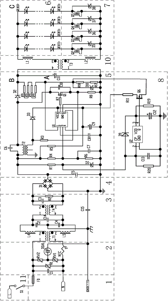
[0035] Such as figure 1 , Figure 3 ~ Figure 6 As shown, this embodiment is a switching and dimming drive circuit for a wide-voltage LED lamp, embedded in the LED lamp, including an overcurrent protection circuit 1, a power supply lightning protection circuit 2, a power supply EMC circuit 3, and an LED light source circuit 6. A rectifier circuit 4 for changing the alternating current of the power supply into direct current, a constant current source circuit 7 for stabilizing the LED light source circuit 6, a voltage stabilizing and PFC circuit 5, a dimming control circuit 8, and a light source EMC circuit 10, The overcurrent protection circuit 1 is connected to the input terminal of the power supply for overcurrent and short circuit protection. The overcurrent protection circuit 1 includes an overcurrent protection fuse F0, and the power supply lightning protection circuit 2 is connected to the rectifier circuit 4 Previously, it was used for lightning protection, including pi...

Embodiment 2

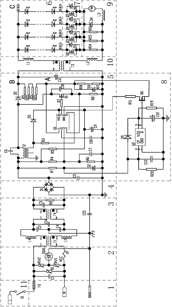
[0042] Such as figure 2 As shown, the difference between this embodiment and Embodiment 1 is that in this embodiment, each group of the constant current source circuits 7 includes an N-channel junction field effect transistor (J-FET) Q2, ..., Q5, The drain of each of the N-channel junction field effect transistors Q2, ..., Q5 is a contact, and the source and gate of each of the N-channel junction field-effect transistors Q2, ..., Q5 are short connected to form another contact, that is, this embodiment uses an N-channel junction field-effect transistor to replace the N-channel depletion-type field-effect transistor in Embodiment 1, and the functions and effects realized by the two are the same; in addition, the wide voltage The switch and dimming driving circuit of the LED lamp also includes a cooling fan circuit 9, the cooling fan circuit 9 is connected in series with the LED light source circuit 6 and the constant current source circuit 7, and the cooling fan circuit 9 inclu...

Embodiment 3

[0045] Such as Figure 7 As shown, this embodiment is a dimming control system for LED lamps, including several parallel LED lamps DS1, DS2, ..., DS(n) and a shared power switch S0, each of the LED lamps DS1, DS2 , ..., DS(n) all include the switch dimming drive circuit of the wide-voltage LED lamp in the first embodiment, through the power switch S0, each of the LED lamps DS1, DS2, ..., DS(n) Perform dimming control. Therefore, the LED lamp dimming control system of this embodiment can conveniently perform large-scale synchronous dimming of multiple LED lamps without a dimmer, and can centrally control multiple lamps, which is conducive to saving electric energy, and is especially suitable for large places Such as the dimming operation of LED lights in cinemas, gymnasiums, etc.


PUM


Abstract

The invention discloses a wide-voltage-range LED lamp switching and dimming driving circuit and an LED lamp dimming control system. The LED lamp dimming control system comprises a plurality of parallel-connected LED lamps and a shared power switch (S0); every LED lamp comprises a switching and dimming driving circuit, and the LED lamps are dimmed simultaneously through the power switch (S0); every switching and dimming driving circuit comprises an LED light source circuit (6), a rectification circuit (4), a constant-current source circuit (7), a stabilizing and PFC (power factor correction) circuit (5), and a dimming control circuit (8) used for generating pulse output signals, adjusting pulse width modulation duty ratio and periodically outputting pulse signals; the output end of the dimming control circuit (8) is connected with the sampling voltage end (A) of the voltage output end (B) of the stabilizing and PFC circuit (5); under the control of the power switch circuit (11), the dimming control circuit (8) can generate pulse switch signals of different duty ratios to control the stabilizing and PFC circuit (5) to provide time-share switch voltage to the LED light source circuit (6) and further to perform power control and dimming on the LED light source circuit (6). The wide-voltage-range LED lamp switching and dimming driving circuit and the LED lamp dimming control system can be applied to the field of LED lamp dimming.

Description

technical field [0001] The invention relates to a switch dimming driving circuit of a wide-voltage LED lamp. In addition, the present invention also relates to an LED lamp dimming control system. Background technique [0002] At present, the application of LEDs is becoming more and more extensive, and LED lamps for daily indoor and outdoor lighting are also becoming more and more popular. Traditional incandescent lamps and fluorescent lamps can be configured with dimmers for dimming, and the output illuminance of the lights can be adjusted to meet people's needs. There is also a need for dimming LED lights, but due to the particularity of LED lights, traditional dimming circuits often cannot adapt to LED lights. The applicant once applied for the Chinese invention patent of "LED lamp energy-saving control circuit" on January 22, 2009. Realize timing two-stage dimming function. However, this kind of circuit cannot realize dimming of LEDs at any time, and the number of dim...

Claims


Application Information

Patent Timeline
Patent Type & Authority Applications(China)
IPC IPC(8): H05B37/02
Inventor 吴俊纬
Owner SHENZHEN ANDYSOM LIGHTING CO LTD
Why Eureka
Try Eureka