High-silent type energy-saving vacuum toilet system

An energy-saving and silent technology, applied in flushing toilets, water supply devices, buildings, etc., can solve problems such as low vacuum, insufficient atmospheric pressure, weak suction, etc., and achieve the effect of low noise

Inactive Publication Date: 2015-06-17
宋志远 +2
View PDF4 Cites 2 Cited by
  • Summary
  • Abstract
  • Description
  • Claims
  • Application Information

AI Technical Summary

Problems solved by technology

[0013] In addition, the vacuum degree of many vacuum toilet systems is very small, so that the atmospheric pressure of the dirt acting up and down is not enough, so that the suction is weak, the time is prolonged, and even the suction cannot be completed during the working hours, so that the residual dirt remains in the toilet. internal, or even unable to work, etc.
[0014] Due to these two major defects, the promotion of vacuum toilet system is hindered

Method used


Image

  • High-silent type energy-saving vacuum toilet system
  • High-silent type energy-saving vacuum toilet system

Examples


Embodiment 1

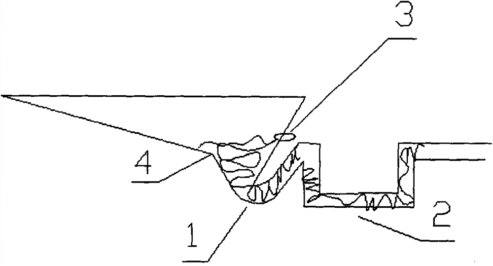
[0024] The first water trap (1) plays the role of avoiding odor and increasing the flow rate, and the second water trap (2) forms a water column, which seems to pull the piston in the pipeline when the toilet is drawn.

[0025] When the toilet is pumped out, the piston is pulled by the action of the second trap (2), and the inside of the toilet is a conical horizontal liquid level drain (4) from the inside of the toilet to the mouth of the pipeline. The inner wall of the toilet flows down at the same speed, and the piston effect is formed by the rear pipe, so that the level of the liquid level in the toilet can be lowered, so that the air from the toilet to the mouth of the first trap pipe basically does not enter, greatly reducing the noise. Can achieve the comfort of advanced siphon toilet.

[0026] When there is too much liquid in the toilet (such as after washing the mop), the probe probe (3) on the second trap (2) works at this moment, and when the liquid inside the toile...

Embodiment 2

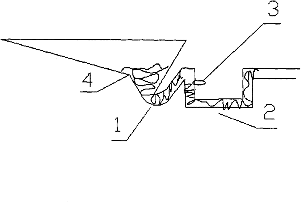
[0028] The first water trap (1) plays the role of avoiding odor and increasing the flow rate, and the second water trap (2) forms a water column, which seems to pull the piston in the pipeline when the toilet is drawn.

[0029] After pressing the flushing button, the toilet is flushed and then pumped. Before the toilet is pumped, the probe probe (3) is soaked in the liquid. When the toilet is pumped, it is the same as the principle of scheme 1. The liquid level in the toilet drops. When the liquid level leaves the probe When the needle probe (3) is used, the electrode is disconnected, and the controller will delay the toilet pumping action after receiving the signal, so as to pump the liquid through the first water trap (1) and then lie down to avoid odor. It is also a liquid piston Flow, basically no air enters, greatly reduces noise, and can achieve the comfort of a high-grade siphon toilet.


PUM


Abstract

The invention provides a high-silent type energy-saving vacuum toilet system which comprises a horizontal liquid surface water falling opening, two water storage elbows, a probe and a closestool. When the closestool is cleaned, piston pulling is formed due to the action of the second water storage elbow so that water liquid close to the same liquid surface of the inner wall of the closestool can flow down from the inner wall of the closestool to the equal conical horizontal liquid surface water falling opening at the pipeline opening of the first water storage elbow at equal speed, and accordingly the effect that the water liquid plane in the closestool slowly descends is achieved, air hardly enters from the inner wall of the closestool to the pipeline opening of the first water storage elbow, a high vacuum degree is achieved, and the effect of greatly lowering noise is achieved; besides, sewage temporarily stored in the second water storage elbow is isolated by clean water of the first water storage elbow, and accordingly odor leakage is avoided; the toilet is flushed one time with over zero point zero kilowatt of electricity and one liter of water, and the aims of saving energy and saving water resources can be truly achieved.

Description

Technical field [0001] The technology of the present invention relates to a vacuum toilet system, in particular to the invention of a high-quiet energy-saving vacuum toilet system using a horizontal liquid level drain, double traps and probe probes. Background technique [0002] The vacuum toilet system was developed in our country in the late 1990s. After years of experiments, it has been proved that there are many advantages: [0003] 1. The suction power of the vacuum toilet is much greater than that of the ordinary gravity flush toilet, so that the urinal can be discharged cleanly and the water consumption is less, generally only about 1 liter per time, and the water consumption of the toilet can be saved by 80%, which is especially suitable in arid areas; [0004] 2. The vacuum toilet system relies on the vacuum in the pipeline to transport sewage. The sewage flows fast, and the sewage crystallization is not easy to occur in winter, and the pipeline is not easy to block...

Claims


Application Information

Patent Timeline
Patent Type & Authority Applications(China)
IPC IPC(8): E03D11/16E03D11/18
Inventor 宋志远罗贾蓉陈彬
Owner 宋志远
Why Eureka
Try Eureka