
Coaxial bi-directional double quick-acting shaft division pluripotent helicopter speed reducer

A coaxial and reducer technology, which is applied in the direction of mechanical equipment, transmission devices, gear transmission devices, etc., can solve the problems of large volume, unsatisfactory use requirements, and large heat generation.

Inactive Publication Date: 2015-06-17
钱金虎
View PDF0 Cites 2 Cited by
  • Summary
  • Abstract
  • Description
  • Claims
  • Application Information

AI Technical Summary

Problems solved by technology

At the same time, there are shortcomings such as large volume, low speed ratio, low efficiency, short life, high heat generation, low reliability, and short maintenance cycle to varying degrees, which cannot meet the requirements of use. Especially in the aviation field, this contradiction is particularly prominent. , the weight of the main reducer on the helicopter accounts for 1 / 7-1 / 9 of the weight of the whole machine; the tail rotor speed change device, the fan and two sets of lubrication mechanisms specially configured for the main reducer have not been counted, divided into three to four In order to meet the requirements, it needs to be decelerated to meet the requirements; and the reliability is poor. In the case of lack of oil lubrication, it can generally only run for half an hour. Now the main reducer of Apache helicopters in the United States can only reach one hour at most.

Method used


Image

  • Coaxial bi-directional double quick-acting shaft division pluripotent helicopter speed reducer
  • Coaxial bi-directional double quick-acting shaft division pluripotent helicopter speed reducer
  • Coaxial bi-directional double quick-acting shaft division pluripotent helicopter speed reducer

Examples


Embodiment Construction

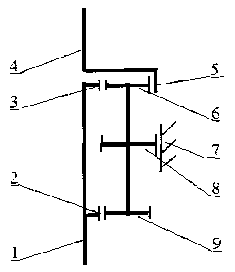
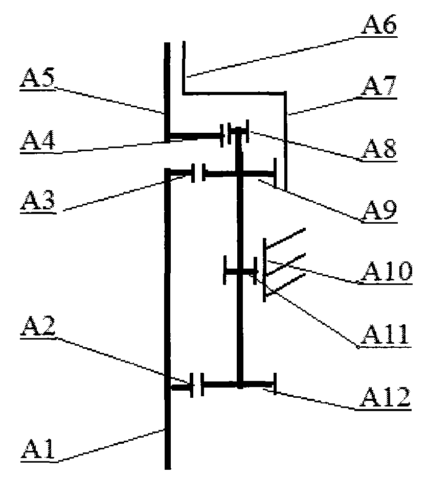
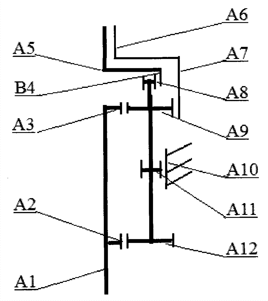
[0010] figure 1 Shown: the same two sun gears 2 and 3 on the input shaft 1 mesh with the two identical gears 6 and 9 on the planetary shaft, and the planetary shaft gear 8 meshes with the fixed outer ring gear 7, of which the sun gear 3, the planetary shaft gear 6, Both the planetary shaft gear 8 and the fixed external ring gear 7 are herringbone gears, and together they form a stable rotating body. The planetary shaft gear 6 meshes with the output external ring gear 5 . figure 2 , image 3 is in figure 1 Structure A gear is added to the output end of the planetary gear shaft to mesh with the sun gear or the outer ring gear at the output end to form a composite structure of coaxial bidirectional and double-speed output.

[0011] When the speed reducer of the present invention is in working state: the power is input by the input shaft 1, through the sun 2, 3, the outer ring gear 7 and the planetary gear shaft are shifted and shifted, and then merged into the outer ring gear ...


PUM


Abstract

The invention provides a coaxial bi-directional double quick-acting shaft division pluripotent helicopter speed reducer. The speed reducer is compact, large in speed ratio and torque, small in size, high in efficiency and long in service life, and is rarely maintained. According to the speed reducer, a planet gear shaft is used for replacing a planet gear in a planetary gear train and meshed with two identical sun wheels in an input shaft, an outer gear ring is meshed with the other gear in the planet gear shaft to form a stable rotating body, the outer gear ring is fixed, and a gear at the front end of the planet gear shaft is meshed with the other outer gear ring to output power to form the planet gear shaft train speed reducer. The speed ratio is mainly decided by the diameter of the two outer gear rings, by combining the diameter changes of the sun wheels and the gears on the planet shaft, rotating speed input by 1 / 3-1 time can be achieved, and revere use is achieved; one gear is additionally arranged at the front end of the planet shaft and meshed with the outer gear rings or the sun wheels to form double-speed output; one gear is additionally arranged at the rear end of the planet shaft and meshed with the outer gear rings or the sun wheels to form division output. Due to the special structure and the high functional property, the speed reducer can be widely applied to the mechanical industry.

Description

technical field [0001] The invention relates to a speed reducer, in particular to a coaxial, bidirectional, double-speed moving shaft split-motion multi-energy helicopter speed reducer. Background technique [0002] Now all kinds of reducers mainly change high speed to low speed and increase torque for use. At the same time, there are disadvantages such as large volume, low speed ratio, low efficiency, short life, high heat generation, low reliability, and short maintenance cycle to varying degrees, which cannot meet the requirements of use. Especially in the aviation field, this contradiction is particularly prominent. , the weight of the main reducer on the helicopter accounts for 1 / 7-1 / 9 of the weight of the whole machine; the tail rotor speed change device, the fan and two sets of lubrication mechanisms specially configured for the main reducer have not been counted, divided into three to four In order to meet the requirement, it needs to reduce the gear step to meet th...

Claims


Application Information

Patent Timeline
IPC IPC(8): F16H1/46
CPCF16H1/46
Inventor 钱金虎
Owner 钱金虎
Learn More