
Induction type water faucet based on pilot structure

An inductive, faucet technology, applied in the valve shell structure, the device used to relieve pressure on the sealing surface, the valve operation/release device, etc., can solve the problems of high energy consumption and the overall structure is not flexible enough to avoid The waste of water resources, the simple and flexible mechanism design, the effect of reducing the opening force

Inactive Publication Date: 2015-06-17
UNIV OF JINAN
View PDF8 Cites 3 Cited by
  • Summary
  • Abstract
  • Description
  • Claims
  • Application Information

AI Technical Summary

Problems solved by technology

[0003] The patent of the present invention provides an inductive faucet based on a pilot structure to solve the problems of inflexible overall structure and high energy consumption in the above-mentioned background technology

Method used


Image

  • Induction type water faucet based on pilot structure
  • Induction type water faucet based on pilot structure
  • Induction type water faucet based on pilot structure

Examples


Embodiment

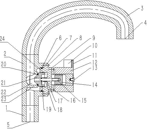
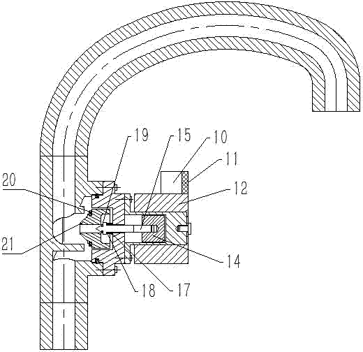
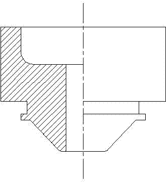
[0022] Such as figure 1 , figure 2 , image 3 , Figure 4 As shown, this embodiment includes a water pipe main body. The water pipe main body includes three parts: the bottom 1 of the main body, the middle part 2 of the main body, and the top 3 of the main body. The main body cover 7 is connected, and the main body cover sealing ring 6 is arranged between the main body cover 7 and the main body middle part 2. The main body cover 7 is fixedly connected with a static armature seat 9, and an electromagnetic coil 12 is provided outside the static armature seat 9. A fixed screw 13 is provided between the top of the static armature seat 9 and the electromagnetic coil 12; a micro-controller 10 and an inductor 11 are fixedly connected above the electromagnetic coil 12, and the micro-controller 10 and the inductor 11 are connected by wires; the static armature seat 9 A movable armature 14 is arranged in the internal clearance, and a small piston rod 15 is provided for the threaded...


PUM


Abstract

The invention belongs to the technical field of water faucet equipment and in particular relates to an induction type water faucet based on a pilot structure. The induction type water faucet comprises a water pipe main body, wherein the water pipe main body comprises a main body bottom part, a main body middle part and a main body top part; a main body cover is fixedly connected to the main body middle part; a main body cover sealing ring is arranged between the main body cover and the main body middle part in a matched mode; a static armature seat is fixedly connected to the main body cover; an electromagnetic coil is arranged outside the static armature seat in a matched mode; a micro controller and an inductor are fixedly connected above the electromagnetic coil; the micro controller is connected with the inductor by virtue of a wire; a moving armature is in clearance fit with the interior of the static armature seat; the left side of the moving armature in threaded connection with a small piston rod; a main body cover inner cavity is formed inside the main body cover; a large piston is in clearance fit with the interior of the main body cover inner cavity; a sealing cylinder is arranged on the main body middle part; and a large piston sealing ring is arranged between the large piston and the sealing cylinder in a matched mode.

Description

technical field [0001] The patent of the invention belongs to the technical field of faucet equipment, and in particular relates to an induction faucet based on a pilot structure. Background technique [0002] Faucets are used in our daily life, whether they are at home or in public places. The original taps were cast in bronze, later switched to less expensive brass. With the rapid development of the changing economy of the times, the faucet industry has also undergone tremendous changes. According to the material, it can be divided into SUS304 Stainless steel , cast iron, all plastic, brass , Zinc alloy faucets, polymer composite faucets and other categories. However, according to the opening method, the faucet can be divided into spiral type, wrench type, lifting type and induction type. When the screw-type handle is opened, it needs to be rotated many times; the wrench-type handle generally only needs to be rotated 90 degrees; In daily life, the spiral type, wrenc...

Claims


Application Information

Patent Timeline
IPC IPC(8): F16K1/00F16K1/38F16K27/02F16K39/02F16K31/06F16K31/12
CPCF16K1/00F16K1/38F16K27/02F16K31/06F16K31/12F16K39/02
Inventor 昃向博张孟杰崔卫华
Owner UNIV OF JINAN
Learn More