
Novel vertical type oil-gas separator

An oil-gas separator, vertical technology, applied in the field of new vertical oil-gas separator, can solve the problems of large impact, large resistance loss, large volume, etc., and achieve reduced charging volume, small resistance loss, and good separation efficiency Effect

Active Publication Date: 2015-06-17
MCQUAY AIR CONDITIONING & REFRIGERATION WUHAN
View PDF5 Cites 11 Cited by
  • Summary
  • Abstract
  • Description
  • Claims
  • Application Information

AI Technical Summary

Problems solved by technology

Among them, the vertical oil separation represented by the cyclone separator mainly throws the oil droplets in the oil-gas mixture to the wall of the cylinder under the action of centrifugal force, so as to realize the separation of oil and gas. The separation efficiency of the cyclone oil-gas separator is high, but it is limited by the cylinder. The external dimensions have a great influence, especially the influence of the inlet mixture flow rate. Generally, the separation efficiency is directly proportional to the inlet flow rate. That is to say, when the unit is operating under partial load, the separation efficiency of the cyclone separator will decrease; Due to the high inlet flow velocity and large resistance loss, it has a certain impact on the operating efficiency of the unit
The horizontal oil separator with the filter screen as the main separation element can meet the oil-gas separation requirements of the unit under different working conditions, and the resistance loss is small at the same time, but it is too large and needs to be filled with a large amount of lubricating oil. Difficult to install

Method used


Image

  • Novel vertical type oil-gas separator
  • Novel vertical type oil-gas separator
  • Novel vertical type oil-gas separator

Examples


Embodiment Construction

[0022] In order to make the object, technical solution and advantages of the present invention clearer, the present invention will be further described in detail below in conjunction with the accompanying drawings and embodiments. The specific embodiments described here are only used to explain the present invention, not to limit the present invention. In addition, the technical features involved in the various embodiments of the present invention described below can be combined with each other as long as they do not constitute a conflict with each other.

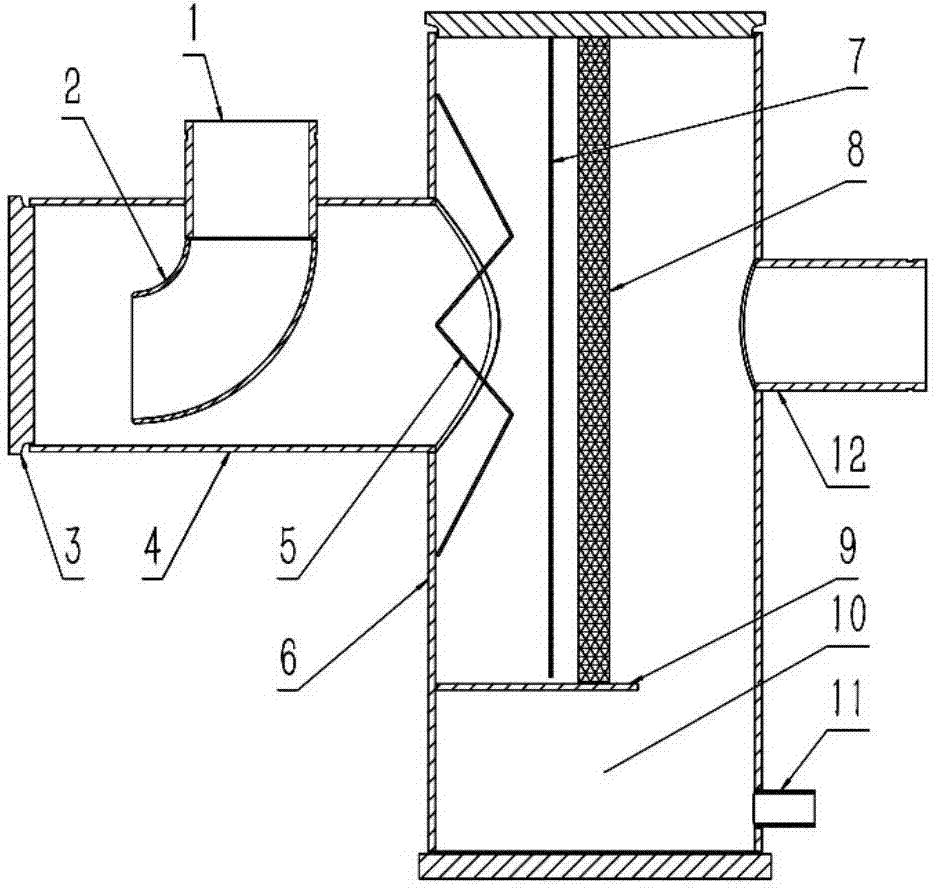
[0023] Such as figure 1 The new vertical oil-gas separator shown includes a horizontal cylinder 4 and a vertical cylinder 6 that are orthogonal to each other, a centrifugal separation section arranged inside the horizontal cylinder 4, and an end cover that closes the horizontal cylinder 4 to form an internal space. 3. The centrifugal separation section of the present invention is composed of an elbow pipe 2, and the angle...


PUM

PropertyMeasurementUnit
Apertureaaaaaaaaaa

Abstract

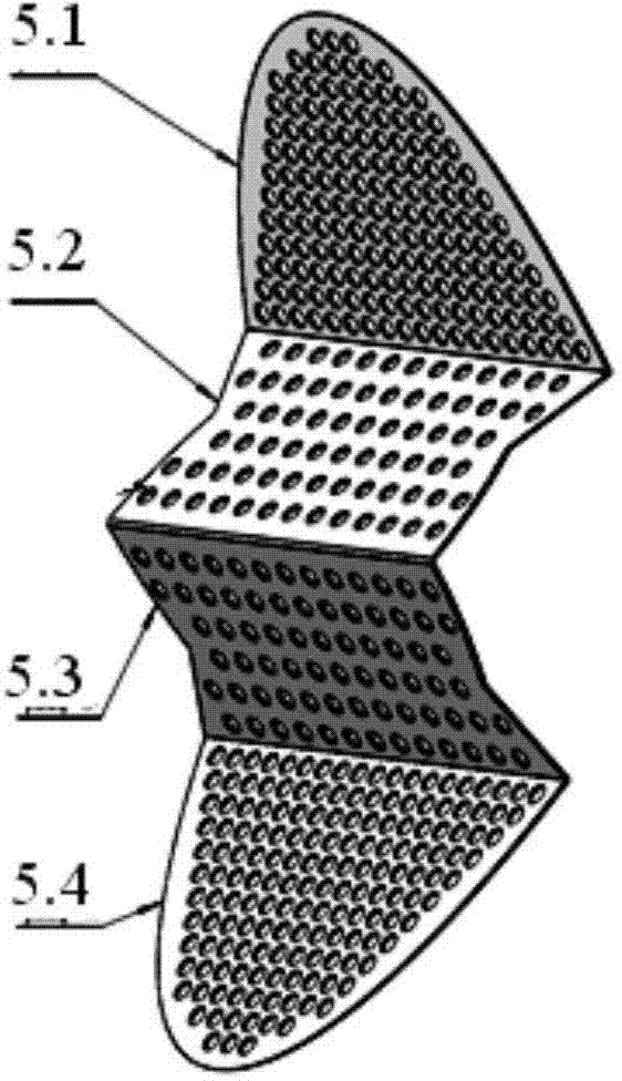
The invention discloses a novel vertical type oil-gas separator. Oil-gas mixtures enter the oil-gas separator through a bending pipeline, centrifugal separation is formed in the bending pipeline, the oil-gas mixtures form collision separation with the wall surface of a horizontal barrel body after coming out from the bending pipeline, the oil-gas mixtures reversely flow after being collided, after the oil-gas mixtures penetrate through a W-shaped baffling perforated plate and a vertical perforated plate, part of oil drops are caught by the wall surfaces of the baffling perforated plate and the vertical perforated plate, and the oil-gas mixtures pass through a filter screen at uniform flow velocity to be filtered and separated so that the surplus oil drops are separated out. Multiple stages of separating devices are utilized to separate the oil drops out from the oil-gas mixtures, the separating efficiency is not affected by the machine set running state, and on the premise that the separating efficiency is met when a machine set is run at full load, the separating efficiency under other load is also very good; the oil-gas mixtures are very small in resistance loss through collision and filter screen separation; filling of lubricating oil is mainly located on a vertical barrel body section, and the filling volume of the lubricating oil is reduced.

Description

technical field [0001] The invention relates to a refrigeration system, in particular to a novel vertical oil-gas separator. Background technique [0002] The oil-air separator is one of the key components in the refrigeration system. A high-quality oil-air separator can not only ensure the high-efficiency operation of the compressor, but also avoid the influence of lubricating oil on the heat transfer performance of the heat exchanger of the unit, and improve the efficiency of the refrigeration unit. performance. At present, the oil-gas separators used in the refrigeration industry mainly have three types in shape: vertical, horizontal and spherical. Among them, the vertical oil separation represented by the cyclone separator mainly throws the oil droplets in the oil-gas mixture to the wall of the cylinder under the action of centrifugal force, so as to realize the separation of oil and gas. The separation efficiency of the cyclone oil-gas separator is high, but it is limi...

Claims


Application Information

Patent Timeline
IPC IPC(8): F25B43/02
CPCF25B43/02
Inventor 徐峰郭丛波张林波罗雄罗毅
Owner MCQUAY AIR CONDITIONING & REFRIGERATION WUHAN
Learn More