Critical speed flow metering system

A flow measurement and critical velocity technology, which is applied in the direction of volume/mass flow generated by mechanical effects, and the detection of fluid flow by measuring differential pressure. Achieve the effect of improving measurement efficiency and measurement accuracy, improving use safety, and preventing loosening

Active Publication Date: 2015-06-17
DEYANG DIXINJIA VALVE MFR
View PDF5 Cites 2 Cited by
  • Summary
  • Abstract
  • Description
  • Claims
  • Application Information

AI Technical Summary

Problems solved by technology

However, when the relevant pressure data and temperature data are digitally and automatically collected in this patent, the flow rate needs to be calculated manually, which has the disadvantages of low calculation efficiency, low accuracy of calculation results and high manual labor intensity.

Method used


Image

  • Critical speed flow metering system
  • Critical speed flow metering system
  • Critical speed flow metering system

Examples


Embodiment 1

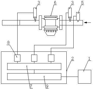
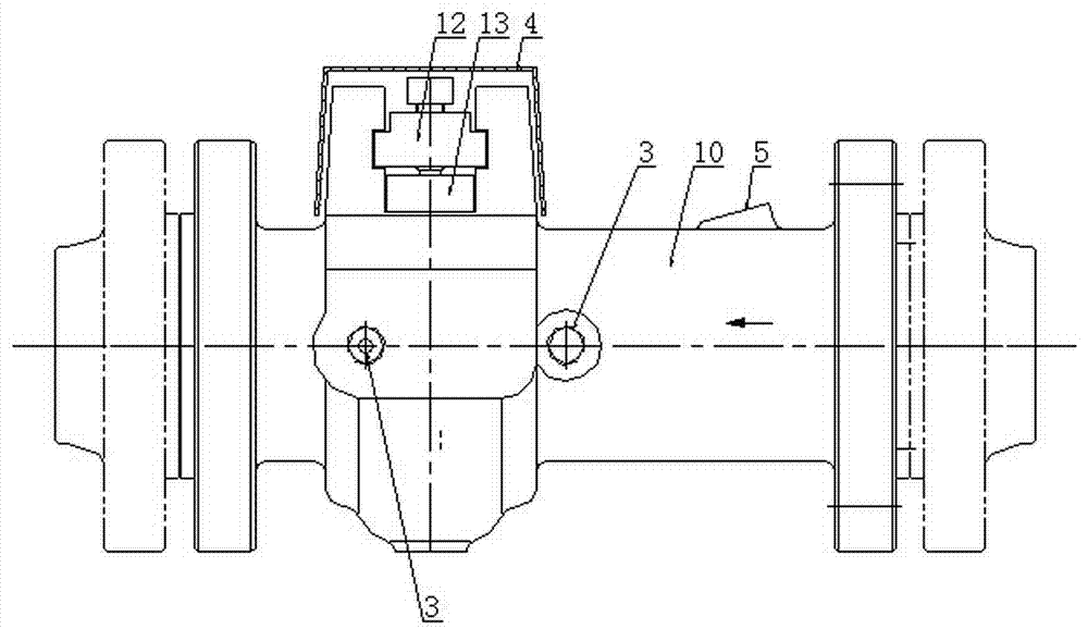
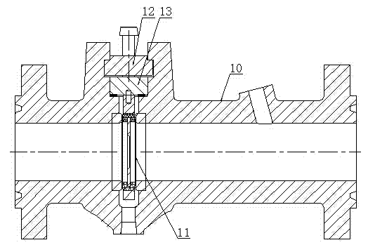
[0024] A critical speed flow metering system, comprising a throttling mechanism 6 and a data acquisition and measurement mechanism, the throttling mechanism 6 includes a valve body 10 and an orifice 11 arranged in the valve body 10, and the data acquisition and measurement mechanism includes a PC 1. Control box 2, temperature sensor 5 and two pressure transmitters 3, the temperature sensor 5 and the two pressure transmitters 3 are fixed on the valve body 10, and one of the pressure transmitters 3 is located in the hole On the downstream side of the plate 11, another pressure transmitter 3 and a temperature sensor 5 are located on the upstream side of the orifice plate 11; the control box 2 is provided with a data acquisition module 7 and a communication module 9, and the temperature sensor 5 and two The pressure transmitters 3 are all connected to the data acquisition module 7, and the data acquisition module 7 transmits the collected data to the PC 1 through the communication ...

Embodiment 2

[0031] A critical speed flow metering system, comprising a throttling mechanism 6 and a data acquisition and measurement mechanism, the throttling mechanism 6 includes a valve body 10 and an orifice 11 arranged in the valve body 10, and the data acquisition and measurement mechanism includes a PC 1. Control box 2, temperature sensor 5 and two pressure transmitters 3, the temperature sensor 5 and the two pressure transmitters 3 are fixed on the valve body 10, and one of the pressure transmitters 3 is located in the hole On the downstream side of the plate 11, another pressure transmitter 3 and a temperature sensor 5 are located on the upstream side of the orifice plate 11; the control box 2 is provided with a data acquisition module 7 and a communication module 9, and the temperature sensor 5 and two The pressure transmitters 3 are all connected to the data acquisition module 7, and the data acquisition module 7 transmits the collected data to the PC 1 through the communication ...


PUM


Abstract

The invention discloses a critical speed flow metering system. The system comprises a throttle mechanism and a data acquiring measurement system, wherein the throttle mechanism comprises a valve body and a pore plate arranged in the valve body, the data acquiring measurement mechanism comprises a PC, a control cabinet, a temperature sensor and two pressure transmitters; the temperature sensor and the two pressure transmitters are fixed on the valve body, one pressure transmitter is located at the downstream side of the pore plate, and the other pressure transmitter and the temperature sensor are located at the upstream side of the pore plate; a data acquiring module and a communication module are arranged in the control cabinet, the temperature sensor and the two pressure transmitters are connected with the data acquiring module, and the data acquiring module is used for transmitting acquired data to the PC by the communication module. The system disclosed by the invention is capable of automatically, accurately and quickly measuring the flow of fluid at the critical speed according to the acquired data, and the aim of integrating data acquisition, transmission and metering is realized.

Description

technical field [0001] The invention relates to the field of fluid flow measurement, in particular to a critical velocity flow metering system, which is mainly used for critical velocity flow metering in the flow test process of natural gas mines and new wells. Background technique [0002] Natural gas flows through the orifice plate to generate throttling, when the upstream pressure P 1 greater than the downstream pressure P 2 About double, that is, P 2 ≤0.546P 1 , the critical airflow is reached. In critical gas flow, the flow velocity of natural gas is equal to the sound velocity of natural gas at the temperature at the minimum flow section. At this time, further reducing the external pressure at the outlet of the orifice plate will not increase the gas production at all, but increasing the upstream pressure will not increase the flow velocity at the minimum section, but will increase the density and increase the gas flow. It shows that the gas flow has nothing to do...

Claims


Application Information

Patent Timeline
Patent Type & Authority Applications(China)
IPC IPC(8): G01F1/36
Inventor 黄斌吴顺利刘波袁弘彬
Owner DEYANG DIXINJIA VALVE MFR
Why Eureka
Try Eureka