
TSV multi-layer chip bonding method

A multi-layer chip and bonding technology, which is applied in electrical components, semiconductor/solid-state device manufacturing, circuits, etc., can solve problems such as large local stress of fillers, chip stress damage, micro cracks, etc., to avoid the risk of cracks, good The effect of protection, avoiding damage and destruction

Inactive Publication Date: 2015-06-17
NO 771 INST OF NO 9 RES INST CHINA AEROSPACE SCI & TECH
View PDF6 Cites 2 Cited by
  • Summary
  • Abstract
  • Description
  • Claims
  • Application Information

AI Technical Summary

Problems solved by technology

However, since the chip with TSV is very thin, and the local stress of the filling in the through hole is relatively large, it will cause stress damage to the chip during the bonding process of high temperature and high pressure, microcracks, and even splits

Method used


Image

  • TSV multi-layer chip bonding method
  • TSV multi-layer chip bonding method
  • TSV multi-layer chip bonding method

Examples


example 1

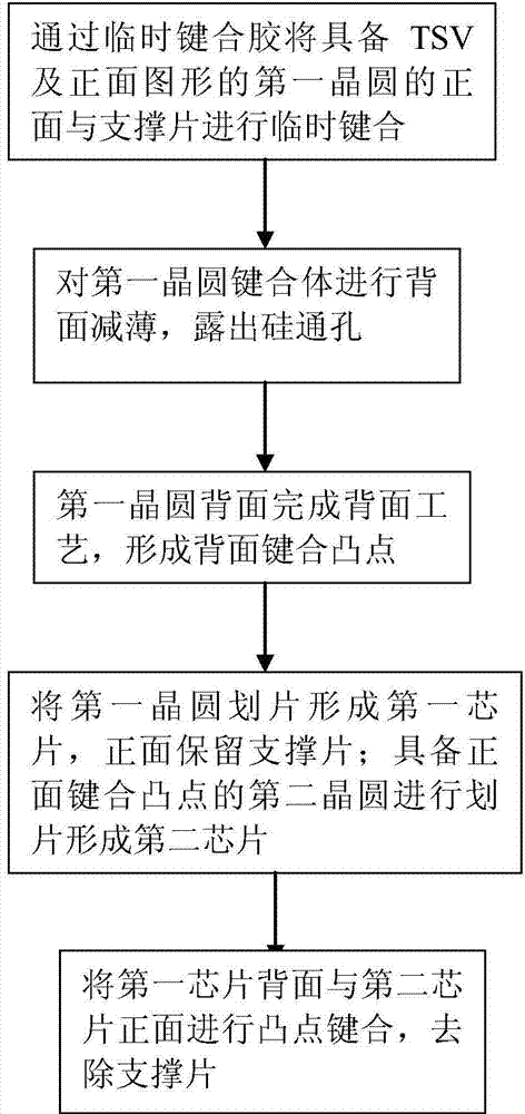
[0037] The present invention provides a kind of TSV multi-layer chip bonding method, and this preferred example is described with two-layer chip and chip bonding method as example, as figure 1 As shown, the method includes: making graphics and bumps on the front of the first wafer, temporarily bonding the front to the support sheet; forming graphics and bonding bumps on the back of the first wafer; cutting the first wafer Round to obtain the first chip, the front of the first chip has a support sheet, and the back has bonding bumps; the second wafer with bumps on the surface is diced to form the second chip; the back bumps of the first chip are combined with the second wafer The front bumps of the two chips are bonded, and the front support sheet of the first chip is removed to obtain a two-layer bonded body between the TSV chip and the chip with the bumps.

[0038] Specifically, the following steps are included,

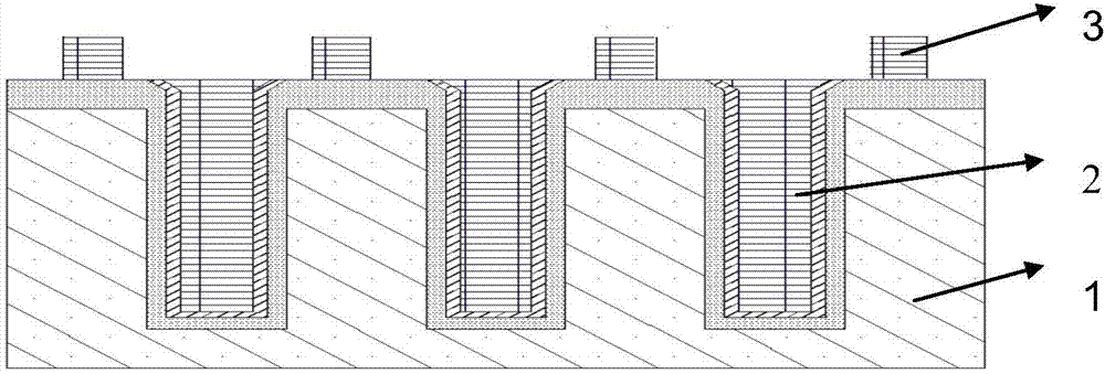
[0039] Step 1, such as image 3 As shown, the first wafer fo...

example 2

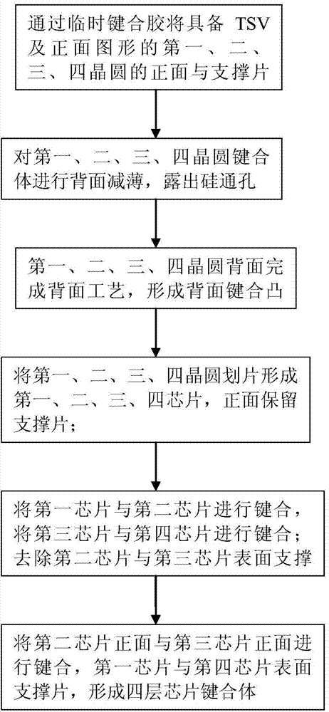
[0046] The present invention provides a kind of TSV multi-layer chip bonding method, and this preferred example uses four-layer chip and chip bonding method, such as figure 2 As shown, the method includes: making graphics and bumps on the front of the first, second or third, and fourth wafers, and temporarily bonding the front to the support sheet; Form graphics and bonding bumps; cut the first, second, third, and fourth wafers to obtain the first, second, third, and fourth chips, the first, second, or third, and fourth chips have support sheets on the front and bonding bumps on the back ; bond the back of the first chip to the back of the second chip or the back of the third chip to the back of the fourth chip; only remove the support sheet on the back of the second chip or the third chip; bond the two-layer bonding body to form four layers Die and die bonded body, remove support sheet.

[0047] Specifically, the following steps are included,

[0048] Step 1, with referenc...


PUM


Abstract

The invention provides a TSV multi-layer chip bonding method including the steps that firstly, the front face of a first wafer with TSV and a front pattern is temporarily bonded to a supporting piece to form a first wafer bonding body; secondly, the back side of the first wafer bonding body is thinned, and a silicon through hole is exposed to form a back side bonding protrusion; thirdly, the bonding body is sliced, the supporting piece is reserved on the front side to form a first chip; fourthly, a second wafer provided with a front side bonding protrusion is sliced to form a second chip; fifth, protrusion bonding is carried out on the first chip and the second chip, and the supporting piece is removed to from a second-layer bonding body; sixthly, protrusion bonding is carried out on chips formed by repeating the first step to the third step according to the step five, sequential bonding and stacking of multiple layers of chips are achieved, and a TSV multi-layer chip is obtained. Or, protrusion bonding is carried out on the chips formed by repeating the first step to the third step in pairs, and a two-layer bonding body with supporting pieces on two sides is formed, and the TSV multi-layer chip is obtained by bonding the chips and / or the two-layer bonding body with the supporting piece on one side removed.

Description

technical field [0001] The invention relates to the field of semiconductor manufacturing, in particular to a TSV multilayer chip bonding method. Background technique [0002] In the semiconductor three-dimensional integration technology, in order to meet the requirements of the device, it is necessary to thin the silicon wafer to a certain thickness to realize the upper and lower interconnection of the channel (TSV, Through Silicon Via) through the silicon wafer. In the thin wafer preparation process with TSVs, the support sheet and the wafer that has completed the TSV front preparation process are first bonded together through a temporary bonding process; then the back side of the wafer is thinned and polished until it reaches Predetermined thickness; then complete the backside preparation process of the wafer, and remove the support sheet to divide the wafer into individual chips; finally perform bump bonding between the chips. However, since the chip with TSV is very thi...

Claims


Application Information

Patent Timeline
IPC IPC(8): H01L21/603H01L21/683
Inventor 吴道伟李克中张波
Owner NO 771 INST OF NO 9 RES INST CHINA AEROSPACE SCI & TECH
Learn More