No current ripple full bridge grid-connected inverter circuit

A full-bridge inverter circuit and inverter circuit technology, applied in the direction of converting AC power input to DC power output, electrical components, output power conversion devices, etc., can solve the problem of increased switching tube loss, unfavorable inverter conversion efficiency, etc. problem, achieve the effect of reducing requirements and improving output current quality

Inactive Publication Date: 2017-11-14
HUZHOU TEACHERS COLLEGE
View PDF6 Cites 0 Cited by
  • Summary
  • Abstract
  • Description
  • Claims
  • Application Information

AI Technical Summary

Problems solved by technology

For this type of inverter, in order to reduce the harmonic content of the grid-connected current and reduce the impact or interference on the grid, it is necessary to increase the switching frequency, and the increase in the switching frequency will lead to an increase in the loss of the switching tube, which is not conducive to the inverter Improvement of converter conversion efficiency

Method used


Image

  • No current ripple full bridge grid-connected inverter circuit
  • No current ripple full bridge grid-connected inverter circuit

Examples


Embodiment 1

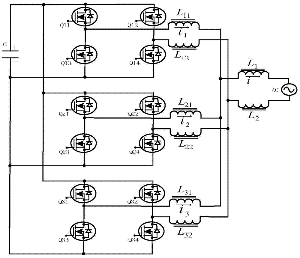
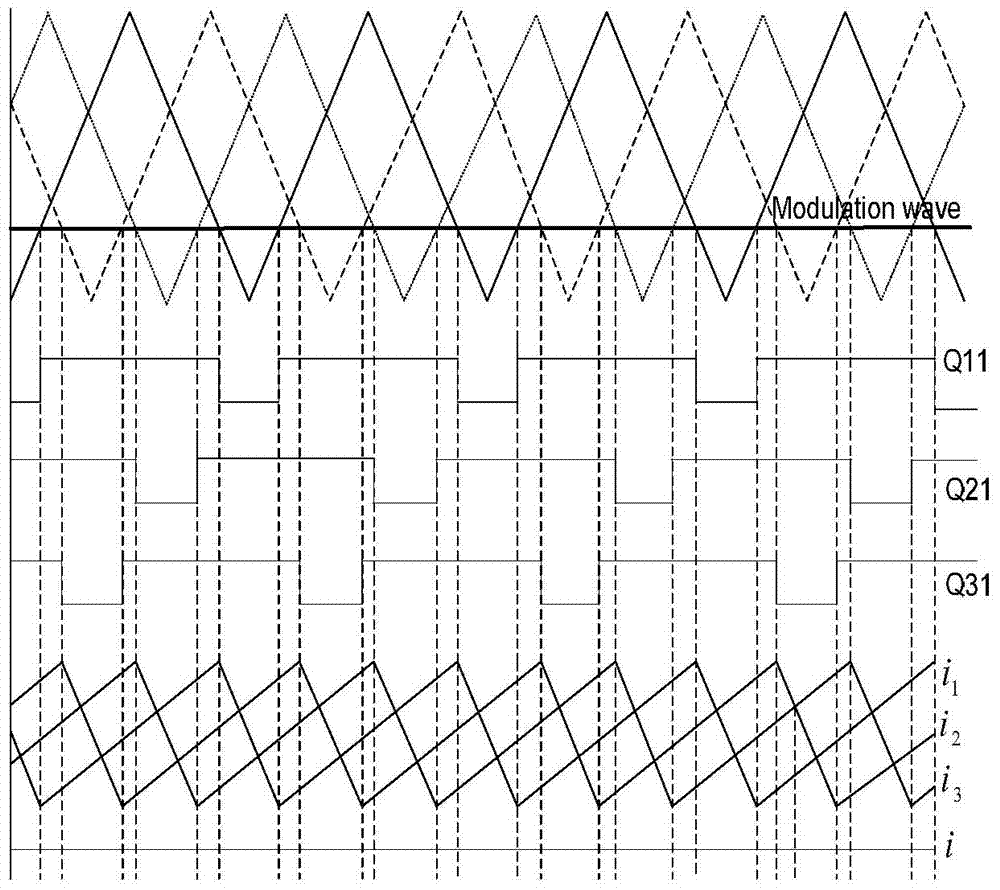
[0013] No current ripple full bridge grid-connected inverter circuit diagram figure 1 In order to connect, the black dots on the two intersecting lines indicate that the two lines are connected to each other, and no black dots indicate that there is no connection between the two lines. figure 1 The three sets of full-bridge grid-connected inverter circuits in the series are connected in parallel, and then connected to the single-phase grid after two filter inductors are connected in series. Each set of full-bridge inverter circuits is composed of four switch tubes and two high-frequency filter inductors. The parallel-connected full-bridge grid-connected inverter circuits respectively output grid-connected currents with equal amplitudes. figure 2 The three sets of parallel full-bridge inverter circuits all adopt unipolar modulation, and the phases of the three sets of high-frequency modulation signal triangular waves are 120° apart, while ensuring that the inductor current in ...


PUM


Abstract

The invention belongs to the field of grid-connected inverter circuit topologies, and relates to a zero-current-ripple full-bridge grid-connected inverter circuit topology which comprises three full-bridge inverter circuits and two filter inductors. Each full-bridge inverter circuit is composed of four switching tubes and two high-frequency filter inductors. The three full-bridge inverter circuits are connected in parallel and then connected to a power grid after the two filter inductors are connected in series. The zero-current-ripple full-bridge grid-connected inverter circuit topology can achieve zero-ripple output of grid-connected current, can also achieve high-quality grid-connected current output even if the work frequency of the switching tubes is low and the filter inductance value is small, and avoids impact and pollution of high-frequency ripples to the power grid.

Description

technical field [0001] The invention relates to a new topology of a grid-connected inverter circuit, which is mainly used in single-phase grid-connected inverters. Background technique [0002] At present, the demand for green energy such as solar energy and wind energy is increasing. Many new grid-connected inverter circuits have been studied. How to improve the conversion efficiency of inverters and reduce the distortion rate of grid-connected current has become the main research content. Currently, the commonly used grid-connected inverter circuit topologies include traditional half-bridge inverter circuit, full-bridge inverter circuit, H5 bridge or H6 bridge three-level inverter circuit. For this type of inverter, in order to reduce the harmonic content of the grid-connected current and reduce the impact or interference on the grid, it is necessary to increase the switching frequency, and the increase in the switching frequency will lead to an increase in the loss of the...

Claims


Application Information

Patent Timeline
Patent Type & Authority Patents(China)
IPC IPC(8): H02M7/493H02M7/5387H02M1/14
Inventor 郭晓瑞
Owner HUZHOU TEACHERS COLLEGE
Why Eureka
Try Eureka