Wireless communication device
A wireless communication device and signal technology, applied in wireless communication, sustainable communication technology, advanced technology and other directions, can solve the problems of intelligent wireless communication terminal heating, battery power decline, WIFI antenna can not adjust the transmission power and other problems
- Summary
- Abstract
- Description
- Claims
- Application Information
AI Technical Summary
Problems solved by technology
Method used
Image

Examples
Embodiment Construction
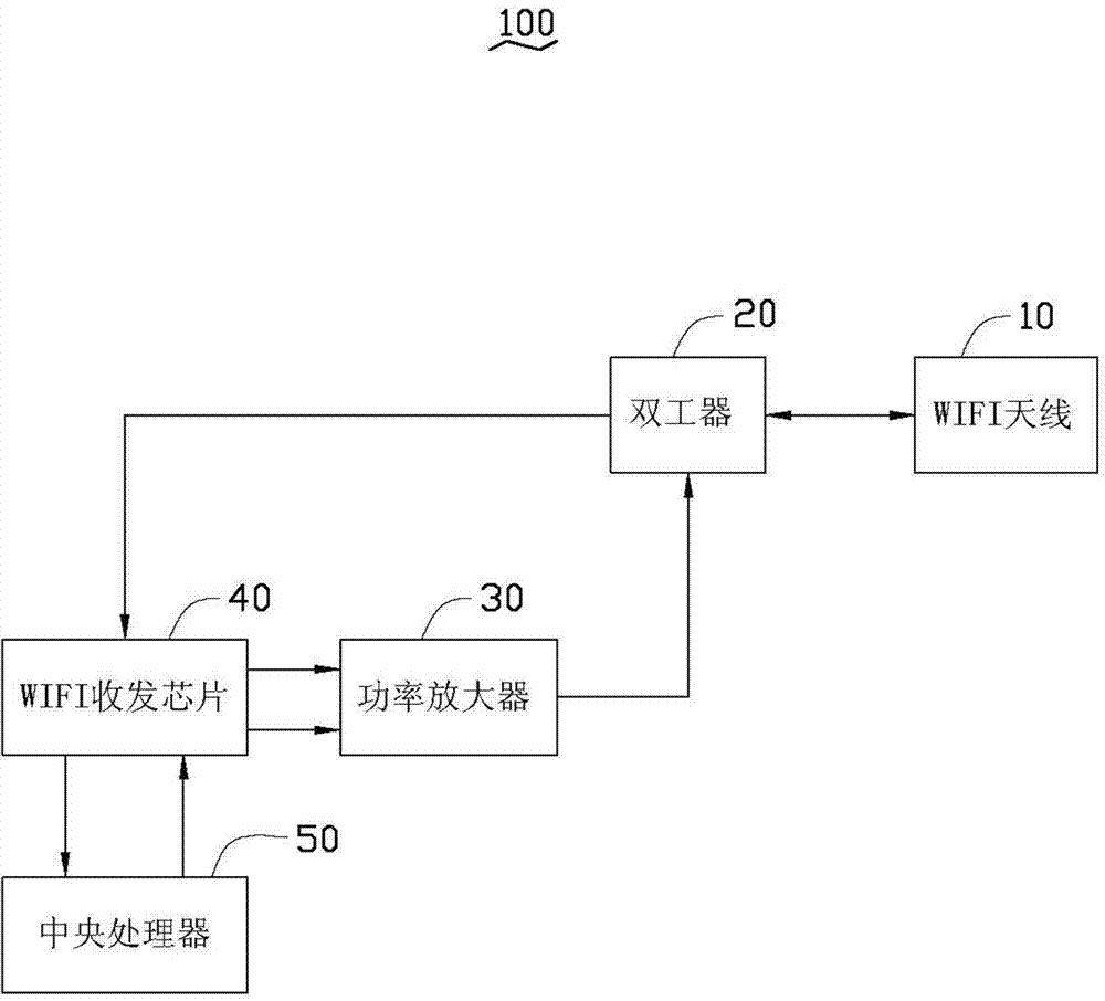
[0011] see figure 1 , a preferred embodiment of the present invention provides a wireless communication device 100, which can be a mobile phone, a personal digital assistant (PDA), a tablet computer and other electronic equipment with a WIFI communication function.
[0012] The wireless communication device 100 includes a WIFI antenna 10 , a duplexer 20 , a power amplifier 30 , a WIFI transceiver chip 40 and a CPU 50 .
[0013] The WIFI antenna 10 is used for receiving WIFI signals from a wireless router or other similar devices, and sending the WIFI signals to the wireless router or other similar devices.
[0014] The duplexer 20 is used to isolate the signal transmission path and the signal reception path of the WIFI signal, and it is electrically connected between the WIFI antenna 10 and the WIFI transceiver chip 30, and is used to transmit the WIFI signal received by the WIFI antenna 10 to the WIFI A transceiver chip 30 . Meanwhile, the duplexer 20 is also electrically c...
PUM
 Abstract
Description
Claims
Application Information
PatSnap Eureka turns technology decisions into work you can execute. Powered by our Innovation Knowledge Graph, it runs expert workflows across engineering, life sciences, materials and intellectual property. Get your review-ready output in minutes.


