Foundation ditch composite concrete nail supporting structure and method

A composite soil nailing and supporting structure technology, applied in foundation structure engineering, excavation, sheet pile wall, etc. Pressure performance, improve the effect of safety and stability

Active Publication Date: 2015-06-24
DALIAN UNIV OF TECH
View PDF6 Cites 10 Cited by
  • Summary
  • Abstract
  • Description
  • Claims
  • Application Information

AI Technical Summary

Problems solved by technology

[0003] (1) In traditional soil nails, the nail head is usually welded to the reinforcing bar or the well-shaped frame steel bar is welded under the nail head. Therefore, prestress cannot be applied to the soil nails, and the soil nails can only be passively stressed, which causes the surface of the foundation pit to be damaged. Both vertical settlement and horizontal deformation are large, which can easily lead to cracking of the pipe network or buildings around the foundation pit
[0004] (2) Since the connection between the nail head and the surface reinforcement mesh is relatively weak, when the force on the soil nail is too large, the nail head is prone to "piercing" damage in the shotcrete surface layer, resulting in failure of the bearing capacity of the soil nail
Since the soil nail needs to be deformed in the foundation pit to play its role, the purpose of the prestressed anchor is to reduce or even eliminate the deformation of the foundation pit, which leads to the uncoordinated force of the soil nail and the prestressed anchor, and the bearing capacity of the two cannot be matched. while being fully exploited
It often leads to the phenomenon that the prestressed anchor first fails and fails due to force, and then the soil nail fails and fails because it cannot support the stability of the foundation pit alone.

Method used


Image

  • Foundation ditch composite concrete nail supporting structure and method
  • Foundation ditch composite concrete nail supporting structure and method
  • Foundation ditch composite concrete nail supporting structure and method

Examples


Embodiment Construction

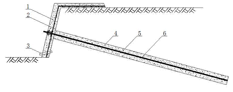
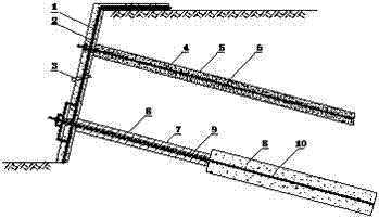
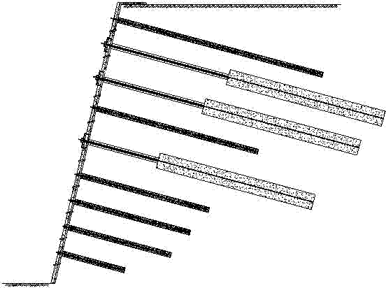
[0070] A kind of foundation pit composite soil nail supporting structure that the present invention proposes has the soil nail 6 that is fixed in the foundation pit wall soil nail borehole 4, the anchor rod 10 that is fixed in the foundation pit wall anchor rod borehole 7, in the foundation pit The surface of the wall is laid with reinforced mesh 2 sprayed concrete and constitutes the retaining surface layer; the soil nails are arranged at intervals in one layer, and the anchor rods are arranged at intervals in the other layer; between the soil nail heads and the reinforced mesh 2 The bearing structure under nailing is installed, and the bearing structure under nailing includes two parallel channel steels 11 arranged on the reinforcement mesh 2, a backing plate 13 placed in the middle of the two parallel channel steels, and the two parallel channel steels 11. The lower flange connecting steel bar 14 and the upper flange connecting steel bar 22 are connected as a whole, and the ...


PUM


Abstract

The invention relates to a foundation ditch composite concrete nail supporting structure and method. The method comprises the steps that concrete nails or anchoring rods are arranged, and a surface layer reinforcing mesh is laid; concrete is injected till the concrete covers the surface layer reinforcing mesh; a lower nail bearing structure is installed; micro-prestress is exerted on the concrete nails, and the concrete nails are locked through nuts; concrete is sprayed to form a block concrete surface layer, and a concrete nail supporting layer is formed; a lower anchor bearing structure is installed; low prestress is exerted on the anchoring rods, and the anchoring rods are locked through anchoring tackles; concrete is injected to form a block concrete surface layer, and an anchoring rod supporting layer is formed; the concrete nail supporting or the anchoring rod supporting is repeated till the supporting reaches the bottom of a foundation ditch, the concrete nail supporting layers and the anchoring rod supporting layers are formed, and the supporting structure is formed. The defects that prestress cannot be exerted on the concrete nails and the nail heads are prone to generating piercing damage to the surface layers are overcome through the lower nail bearing structure of the nail heads of the concrete nails; the problems of steel channel buckling damage and the anchoring head punching failure are solved through the lower anchor bearing structure of the anchoring heads; the defects that work of the concrete nails and work of the anchoring rods are inconsistent in the traditional joint supporting of the concrete nails and the anchoring rods is solved by exerting the micro-prestress on the concrete nails and exerting the low prestress on the anchoring rods.

Description

technical field [0001] The invention relates to a foundation pit composite soil nail support and bolt support structure and a construction method thereof, which are used for reinforcement and support in various foundation pits, side slopes and underground projects. Background technique [0002] In the reinforcement and support technology of foundation pits, slopes and underground engineering, soil nailing technology is widely used, but its engineering application is limited due to the serious problem of large deformation of soil nailing foundation pits. In order to solve the engineering problem of large deformation of the foundation pit supported by soil nails, the construction measures of combining prestressed anchor rods and soil nails are often used in actual projects, and the deformation of the foundation pit is controlled by applying prestress to the anchor rods. Cooperate with the anchor to ensure the overall safety of the foundation pit. But this has created four new...

Claims


Application Information

Patent Timeline
Patent Type & Authority Applications(China)
IPC IPC(8): E02D5/74E02D5/76
CPCE02D5/74E02D5/76E02D17/04
Inventor 贾金青黄强杨志银曾宪明程良奎涂兵雄柳建国范景伦
Owner DALIAN UNIV OF TECH
Why Eureka
Try Eureka