Sewer cleaning machine

A technology for cleaning machines and sewers, applied in the field of cleaning machines, can solve the problems of high labor intensity, slow cleaning speed, and unsatisfactory effects, and achieve the effect of reducing physical labor.

Active Publication Date: 2015-06-24
ANYANG GUOLONG MACHINERY
View PDF6 Cites 8 Cited by
  • Summary
  • Abstract
  • Description
  • Claims
  • Application Information

AI Technical Summary

Problems solved by technology

[0003] Aiming at the problems of slow cleaning speed, unsatisfactory effect, high labor intensity, and risks such as poisoning in the cleaning process in the sewer cleaning work, the invention provides a sewer cleaning machine, the purpose of which is to increase the cleaning speed of the sewer, reduce labor intensity, and reduce waste. Necessary poisoning accidents occur

Method used


Image

  • Sewer cleaning machine
  • Sewer cleaning machine
  • Sewer cleaning machine

Examples


Embodiment 1

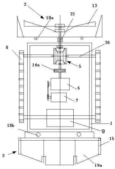
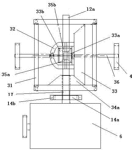
[0014] The technical solution of the present invention is a sewer cleaning machine, figure 1 It is a side view structural schematic diagram of the present invention, figure 2 figure 1 The schematic diagram of the side view structure of A1-A2 in the middle, the sewer cleaning machine is composed of multiple sprockets 4 on both sides, and the left and right pairs of sprockets 4 in the front are respectively connected to the output ends of the left and right half shafts 36 of the differential 5 , the back two sprockets 4 are directly connected on a coaxial left and right direction, and the two front and rear sprockets 4 on the left and right sides are connected by a chain rail 8, and a plurality of tensioning sprockets are also assembled on the chain rail 8 4a, the tensioning sprocket shaft is set on the sprocket frame 20, and the driving device for driving the sprocket 4 is set in a sealed casing 1, and the casing 1 is provided with a motor 7 and a reducer 6 sequentially from ...

Embodiment 2

[0026] Depending on the type and structure of the motor, reducer and differential used, the structure arranged in the housing is also different. Image 6 It is another setting method of the driving device in this technical solution. The same mud turning device and reverse conveying device in the embodiment 1 are arranged in the front and rear of the sealed casing 2 50, and the connection mode is also completely the same.

[0027] The sealed casing two 50 is provided with motor two 51, motor two 51 and the direction of the input shaft of the speed reducer two 53, the motor shaft sprocket two 58a on the output shaft of the motor two 51 and the speed reducer input sprocket two 58b They are connected by chain 2 58c, and the reducer output sprocket 2 58e on the output shaft of reducer 2 53 is connected with the differential input sprocket 2 58f by chain 3 58h. There are two half-shafts with different lengths connected to the differential below, which are respectively left half-shaf...


PUM


Abstract

The invention provides a sewer cleaning machine and belongs to municipal engineering machinery. The sewer cleaning machine comprises a camera, a plurality of chain wheels on two sides, chain rails assembled on the chain wheels, a driving device shell arranged in a sealing mode, a sludge turnover device arranged at the front end, a sludge reverse conveying device arranged on the rear side of the shell, a wireless antenna arranged at the top, a wireless information transmission device connected with the wireless antenna, and a wireless remote control device matched with the wireless information transmission device, an infrared camera is arranged at the upper portion of the shell, and the infrared camera is connected with the information transmission device. Through the cleaning machine, the physical labor intensity of workers can be relieved, the cleaning speed of waste such as sludge in a sewer is increased, and the problems that workers feel unwell and suffer from gas poisoning in the severe operating environment in the sewer can be solved.

Description

technical field [0001] The invention relates to a cleaning machine, in particular to a sewer cleaning machine, which belongs to municipal engineering machinery. Background technique [0002] The sewer is the main channel of municipal drainage. Whether the sewer is smooth or not is directly related to the travel of citizens. It is very important to keep the sewer unblocked all the time. Silt is the main blockage in the sewer. So far, the cleaning of the sewer, It mainly relies on manual cleaning, which requires workers to wear waterproof clothing and drill into the sewer for cleaning. The cleaning speed is low and the cleaning effect is not ideal. Cleaning up garbage in the dark sewer is not only labor-intensive, but also sometimes causes physical allergies, clothes and body Pollution, and even accidents of worker poisoning and death due to excessive concentration of harmful gases in the sewer. How to reduce physical labor and reduce the risks in the cleaning process is a ma...

Claims


Application Information

Patent Timeline
Patent Type & Authority Applications(China)
IPC IPC(8): E03F7/10
Inventor 袁国堂
Owner ANYANG GUOLONG MACHINERY
Why Eureka
Try Eureka