A sewer cleaning machine
A cleaning machine and sewer technology, applied in the field of cleaning machines, can solve problems such as high labor intensity, poisoning, and slow cleaning speed, and achieve the effect of reducing physical labor intensity
- Summary
- Abstract
- Description
- Claims
- Application Information
AI Technical Summary
Problems solved by technology
Method used
Image
Examples
Embodiment 1
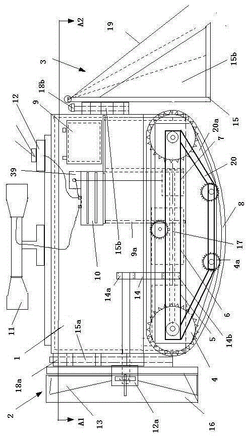
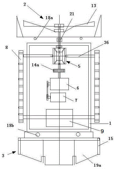
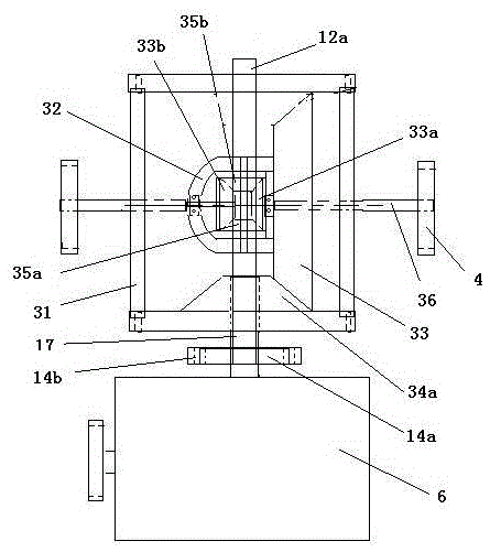
[0014] The technical solution of the present invention is a sewer cleaning machine, figure 1 It is a side view structural schematic diagram of the present invention, figure 2 figure 1 The schematic diagram of the side view structure of A1-A2 in the middle, the sewer cleaning machine is composed of multiple sprockets 4 on both sides, and the left and right pairs of sprockets 4 in the front are respectively connected to the output ends of the left and right half shafts 36 of the differential 5 , the back two sprockets 4 are directly connected on a coaxial left and right direction, and the two front and rear sprockets 4 on the left and right sides are connected by a chain rail 8, and a plurality of tensioning sprockets are also assembled on the chain rail 8 4a, the tensioning sprocket shaft is set on the sprocket frame 20, and the driving device for driving the sprocket 4 is set in a sealed casing 1, and the casing 1 is provided with a motor 7 and a reducer 6 sequentially from ...
Embodiment 2
[0026] Depending on the type and structure of the motor, reducer and differential used, the structure arranged in the housing is also different. Figure 6 It is another setting method of the driving device in this technical solution. The same mud turning device and reverse conveying device in the embodiment 1 are arranged in the front and rear of the sealed casing 2 50, and the connection mode is also completely the same.
[0027] The sealed casing two 50 is provided with motor two 51, motor two 51 and the direction of the input shaft of the speed reducer two 53, the motor shaft sprocket two 58a on the output shaft of the motor two 51 and the speed reducer input sprocket two 58b They are connected by chain 2 58c, and the reducer output sprocket 2 58e on the output shaft of reducer 2 53 is connected with the differential input sprocket 2 58f by chain 3 58h. There are two half-shafts with different lengths connected to the differential below, which are respectively left half-sha...
PUM
 Abstract
Description
Claims
Application Information
 - R&D
- Intellectual Property
- Life Sciences
- Materials
- Tech Scout
- Unparalleled Data Quality
- Higher Quality Content
- 60% Fewer Hallucinations
Browse by: Latest US Patents, China's latest patents, Technical Efficacy Thesaurus, Application Domain, Technology Topic, Popular Technical Reports.
© 2025 PatSnap. All rights reserved.Legal|Privacy policy|Modern Slavery Act Transparency Statement|Sitemap|About US| Contact US: help@patsnap.com


